Element Connectivity
The different elements of the structure are defined in the Element Connectivity module, where their name, element class, corresponding nodes, rigid offsets, force/moment releases and eventually activation time/L.F. are identified.
It is noted that the possibility of defining an activation (and deactivation) time/L.F. is provided within each element. The default values are -1e20 for activation (in order to cater for cyclic pushover analysis) and 1e20 for deactivation; this means that the element is activated at the beginning of any analysis and it will not be deactivated.
As in all other modules, the user is capable of adding new elements (also in the graphical input mode) and removing or editing existing selected elements (see module editing functions). In addition, however, Incrementation and Subdivision facilities are equally available.
As in the case of nodes, element incrementation enables the automatic generation of new elements through "repetition" of existing ones. It functions in very much the same manner as the automatic generation of nodes, with the difference that instead of nodal coordinates, it is the names of element nodes that are incremented. This facility obviously requires that element names respect the number (e.g. 100) or word+number (e.g. elm20) formats.
Element subdivision, on the other hand, serves the purpose of providing the user with a tool for easy and fast subdivision of existing frame elements, so as to refine the mesh in localised areas (for instance to increase the accuracy of the analysis in zones of high inelasticity that have been detected only after running a first analysis with a coarser mesh). The creation of the new internal nodes, the generation of the new smaller elements and the updating of element connectivity is all carried out automatically by the program. Users can subdivide existing elements into 2, 4, 5 and 6 smaller components, the length of which is computed as a percentage of the original element's size, as defined in Element Subdivision.
In what follows, an overview of connectivity requirements for each of the element types available in SeismoStruct is given.
Elastic and inelastic frame elements - infrmDB, infrmFB, infrmFBPH, infrmDBPH, elfrm & elfrmH
Two nodes need to be defined for these element types, representing the end-nodes of the element, thus defining its length, position in space and direction (local axis 1). A rotation angle or a third node is required so as to define the orientation of the element's cross section (local axes 2 and 3), as described in here. Users are advised to make use of the rotation angle or a non-structural, rather than a structural, node in the definition of this third element node. It is also recommended that the same non-structural node comes employed in the third node definition of all beam-column elements positioned within the same plane (see discussion of global and local axes systems).
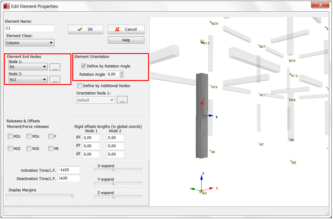
In addition, for each frame element it is possible to specify Rigid offsets lengths (in global coordinates) by assigning a value for dX, dY and dZ to Nodes 1 and 2, respectively. Furthermore, users may also 'release' one or more of the element degrees of freedom (forces or moments) from the joints. It is noted that Moment/force releases are always specified in the element local coordinate system.
Infill panel element - infill
Four nodes need to be defined for this element type. These correspond to the corners of the infill panel, must be entered in anti-clockwise sequence starting from the lower-left-hand corner, and must all belong to the same plane. It is noted that the internal struts 1, 2 and 5 of the panel will then be those connecting its first and third nodes, whilst internal struts 3, 4 and 6 will be made to connect the second and the fourth panel corners.
Inelastic truss element - truss
Two nodes need to be defined for this element type, usually corresponding to the extremities of structural members (i.e. one truss element per each structural member), unless there is a need to model element instability, in which case two or more truss elements (including an initial imperfection) per member should be employed.
Masonry element - masonry
Two nodes need to be defined for these element types, representing the end-nodes of the element, thus defining its length, position in space and direction (local axis 1). A rotation angle or a third node is required so as to define the orientation of the element's cross section (local axes 2 and 3), as described in Global and local axes system.
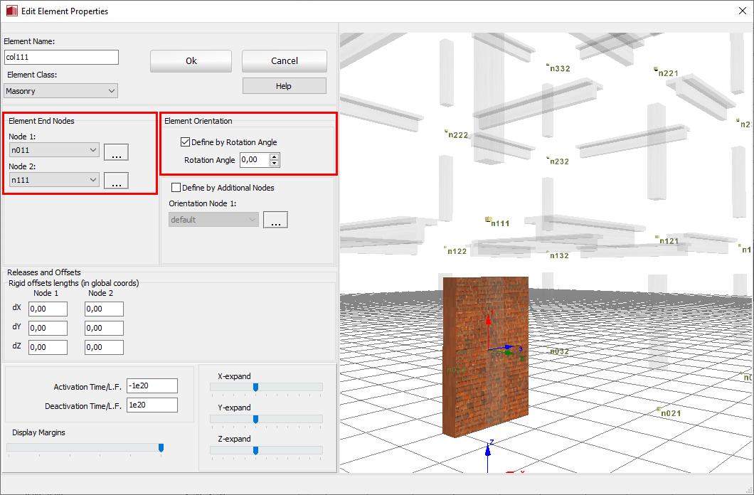
In addition, for each wall element it is possible to specify Rigid offsets lengths (in global coordinates) by assigning a value for dX, dY and dZ to Nodes 1 and 2, respectively.
Rack elements - rack & rackH
Two nodes need to be defined for these element types, representing the end-nodes of the element, thus defining its length, position in space and direction (local axis 1). A rotation angle or a third node is required so as to define the orientation of the element's cross section (local axes 2 and 3), as described in Global and local axes system.
Shell element - shell4
Four nodes need to be defined for this element type. These correspond to the corners of the shell element, must be entered in anti-clockwise sequence starting from the lower-left-hand corner, and must all belong to the same plane.
Link elements - linlink, NLlink, ssi1, ssi2, isolator 1 & isolator 2
Four nodes need to be defined for this element type. The first two are the end-nodes of the element and must be initially coincident since all link elements have an initial length equal to zero. The latter condition implies also that a third node is required to define local axis (1), noting that the orientation of this axis after deformation is determined by its initial orientation and the global rotation of the first node of the element. The fourth node is used to define local axes (2) and (3), following the convention described in global and local axes systems. Instead of the definition of a third and a fourth node, users may simply employ the keyword 'default', which implies that local axis-1 is along the X global axis and local axis-3 is along the Z global axis. Users are advised to make use of non-structural nodes in the definition of the third and fourth element nodes.
Lumped mass element - lmass
A single node needs to be defined for this element type. In building frames subjected to horizontal excitation, it is customary to assign one lumped element at each beam-column connection, although one element per storey will provide sufficient accuracy for the majority of applications (where vertical excitation and axial beam deformation are negligible). When analysing bridges, on the other hand, it is common to concentrate deck inertia mass at pier-deck intersection nodes, unless a more rigorous approach is required [e.g. Casarotti and Pinho, 2006].
Distributed mass element - dmass
Two nodes need to be defined for this element type, usually corresponding to the extremities of structural members (i.e. one dmass element per each column, beam, etc.), unless very large displacements are expected, in which case two or more distributed mass elements per member should be employed.
Dashpot damping elements - dashpt & NLdashpt
A single node needs to be defined for these element types (the second node of the dashpot is assumed to be fixed to the ground).
Notes
- Whilst a too coarse finite element mesh may lead to the impossibility of accurately reproducing certain response shapes/mechanisms, an exaggeratedly mesh refinement (e.g. resulting in frame elements with length much smaller than their cross-section height) may lead to unnecessary long analyses and, in some instances, to less stable solutions. Hence, users are advised to make well balanced and judged decisions on the level of mesh refinement that they decide to introduce, ideally carrying out sensitivity studies in order to define the point of optimum balance between accuracy, numerical stability and analysis' run times.
- A maximum number of 50000 elements may be defined.
- Users can also change in a single operation, for instance, the non-structural node used in a large number of elements, again by taking advantage of the multiple selection and editing features available in this and other modules.