Inelastic displacement-based plastic hinge frame element type - infrmDBPH
This is a displacement-based plastic-hinge 3D beam-column element with concentrated plasticity at the two element’s ends. All nonlinear deformations of the element are lumped in these rotational springs, whereas the rest of the member remains elastic. The DBPH formulation is capable of modelling the geometric nonlinearities.
The element consists of three sub-elements, the two links at the member edges, which model the plastic rotational deformations around the 2nd and the 3rd local axes, and an elastic frame element in the middle, which models the part of the member that remains elastic. The sub-elements are connected in series, and an iterative procedure is required, in order to achieve internal element equilibrium.
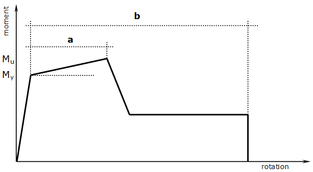
The force-displacements relationships of the four nonlinear rotational springs at the element's ends feature a hysteretic curve that is based on SeismoStruct’s built-in MIMK_bilin nonlinear curve. The yield and ultimate bending moment (My and Mu respectively), as well as the deformation at yield dy are calculated from a moment-curvature section analysis after the application of the initial loads on the structure, taking into account the axial load imposed on the element. Instead, the plastic rotation capacity a and the rotation at ultimate b are estimated directly from ASCE 41-23, and in particular from Tables 10-7 (for beams), 10-8 & 10-9 (for columns) and 10-19 (for walls); see also ASCE 41-23, Figure 10-1 and the figure below for more details.
The moment-rotation curves in the two local axes at each end are independent. This is obviously a simplification with respect to the force-based plastic hinge element, where inelastic deformations spread over a finite region at the ends of the girder and the behaviour in the two local axes is correlated. However this lack of accurate modelling is compensated shorter analysis times. Since the hysteretic curve parameters are automatically calculated by the program, users need only specify the member's section. Similarly to the infrmFB and infrmFBPH elements, the changes in reinforcement details within the same member can be achieved with the use of multiple sections per element.
Apart from the automatic calculation of the plastic hinge properties, SeismoStruct also allows the input of a, b and c values (c being the ratio of the residual to the ultimate strength) that are different from the calculated ones. This can be achieved, if in the Definition of Modelling Parameters drop-down menu the User-defined option is selected. Users are than allowed to freely introduce the plastic hinge modelling parameters. Note however that even in the case of user defined parameters a section should be specified, mainly for display purposes (e.g. to show the member in the 3D plot).
Finally, by clicking the Calculate Hinge Properties button a new dialog box appears that provides assistance in the determination of these parameters, based on several parameters such as the ratio of the area of the distributed longitudinal reinforcement to the gross concrete area rl, the ratio of the area of the distributed transverse reinforcement to the gross concrete area rt, the gross section area Ag, the expected yield strength of the longitudinal and transverse reinforcing steel fylE & fytE, the expected compressive strength of concrete f’cE, the member axial force Nud, whether the member’s shear reinforcement is conforming or not, whether the member is controlled by flexure or shear etc.
It is also possible to define an element-specific damping, as opposed to the global damping defined in here, as described in the sections on infrmFB and infrmFBPH. Finally, local axes and output notation are the same with the force-based elements.
Local Axes and Output Notation