Inelastic force-based frame element type - infrmFB
This is the force-based 3D beam-column element type capable of modelling members of space frames with geometric and material nonlinearities. As described in here, the sectional stress-strain state of beam-column elements is obtained through the integration of the nonlinear uniaxial material response of the individual fibres in which the section has been subdivided, fully accounting for the spread of inelasticity along the member length and across the section depth.
As discussed in Material Inelasticity, element infrmFB is the most accurate among the four frame element types of SeismoStruct, since it is capable of capturing the inelastic behaviour along the entire length of a structural member, even when employing a single element per member. Hence, its use allows for very high accuracy in the analytical results, while giving users the possibility of readily employing element chord-rotations output for seismic code verifications (e.g. Eurocode 8, NTC-18, KANEPE, FEMA-356, ATC-40, etc).
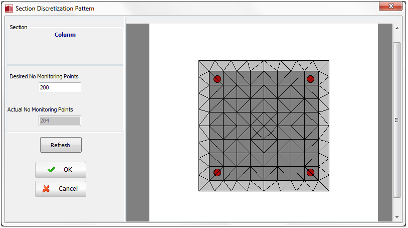
The number of section fibres used in equilibrium computations carried out at each of the element's integration sections needs to be defined. The ideal number of section fibres, sufficient to guarantee an adequate reproduction of the stress-strain distribution across the element's cross-section, varies with the shape and material characteristics of the latter, depending also on the degree of inelasticity to which the element will be forced to. As a crude rule of thumb, users may consider that single-material sections will usually be adequately represented by 100 fibres, whilst more complicated sections, subjected to high levels of inelasticity, will normally call for the employment of 200 fibres or more. However, and clearly, only a sensitivity study carried out by the user on a case-by-case basis can unequivocally establish the optimum number of section fibres.
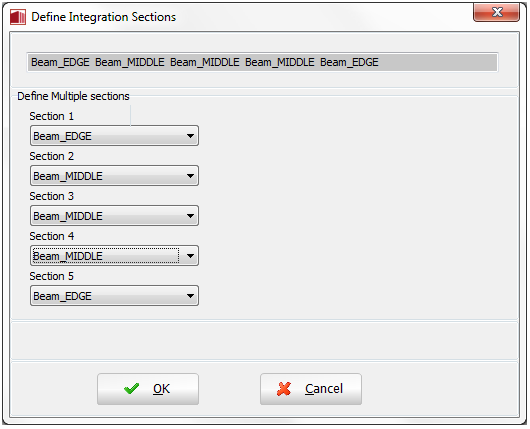
In addition, the number of integration sections needs to be defined. A number between 4 and 7 integration sections will typically be adopted, though users are warmly invited to search the bibliography [e.g. Papadrakakis 2008; Calabrese et al. 2010] for further guidance on this matter (it is recalled that the location of such integration sections across the element's length are indicated in Material Inelasticity). In particular it is noted that up to 7 integrations sections may be needed to accurately model hardening response, but, on the other hand, 4 or 5 integration sections may be advisable when it is foreseen that the elements will reach their softening response range.
Note: Instead of discretizing the elements to represent the changes in reinforcement details (see above), it is possible to use one single infrmFB element per member and then define multiple sections. It is noted that these sections may differ only in the reinforcement (i.e. section type, dimensions and materials have to be the same).
In this element's dialog box it is also possible to define an element-specific damping, as opposed to the global damping described in here. To do so, users need simply to press the Damping button and then select the type of damping that better suits the element in question (users should refer to the Damping menu for a discussion on the different types of damping available and hints on which might the better options). Users are reminded also that damping defined at element level takes precedence over global damping, that is, the "globally-computed" damping matrix coefficients that are associated to the degrees-of-freedom of a given element will be replaced by coefficients that will have been calculated through the multiplication of the mass matrix of the element by a mass-proportional parameter, or through the multiplication of the element stiffness matrix by a stiffness-proportional parameter, or through the calculation of an element damping Rayleigh matrix.
Note: If Rayleigh damping is defined at element level, using varied coefficients from one element to the other, or with respect to those employed in the global damping settings, then non-classical Rayleigh damping is being modelled, classing Rayleigh damping requires uniform damping definition.
Local Axes and Output Notation