Inelastic infill panel element - infill
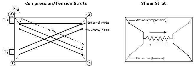
A four-node masonry panel element, developed and initially programmed by Crisafulli [1997] and implemented in SeismoStruct by Blandon [2005], for the modelling of the nonlinear response of infill panels in framed structures. Each panel is represented by six strut members; each diagonal direction features two parallel struts to carry axial loads across two opposite diagonal corners and a third one to carry the shear from the top to the bottom of the panel. This latter strut only acts across the diagonal that is on compression, hence its "activation" depends on the deformation of the panel. The axial load struts use the masonry strut hysteresis model, while the shear strut uses a dedicated bilinear hysteresis rule.
Also as can be observed in the Figure below, four internal nodes are employed to account for the actual points of contact between the frame and the infill panel (i.e. to account for the width and height of the columns and beams, respectively), whilst four dummy nodes are introduced with the objective of accounting for the contact length between the frame and the infill panel. All the internal forces are transformed to the exterior four nodes (which, as noted here, need to be defined in anti-clockwise sequence) where the element is connected to the frame.
Note: Although the inelastic infill panel elements have been created for the modelling of the nonlinear response of infill panels in framed structures (as stated above), they might also be employed for the modelling of slabs with a specific stiffness contribution and inelastic behaviour pattern, e.g. by strategically placing these elements and/or inelastic truss elements with properties set to mimic the desired behaviour (as suggested here).
In order to fully characterise this type of element, the following needs to be defined:
Strut Curve Parameters
Employed in the definition of the masonry strut hysteresis model, which is modelled with the inf_strut response curve.
Shear Curve Parameters
Employed in the definition of the masonry strut hysteresis model, which is modelled with the inf_shear response curve.
Infill Panel Thickness - t
Which may be considered as equal to the width of the panel bricks alone (e.g. 12 cm), or include also the contribution of the plaster (e.g. 12+2x1.5=15 cm).
Out-of-plane failure drift
Introduced in percentage of storey height, and which dictates the de-activation of the element, i.e. once the panel, not the frame, reaches a given out-of-plane drift, the panel no longer contributes to the structure's resistance nor stiffness, since it is assumed that it has failed by means of an out-of-plane failure mechanism. (it is noted that acceleration-triggered de-activation has not been introduced, because it could result very sensitive to high frequency and/or spurious acceleration modes. However, a workaround is nonetheless suggested in note 5, below).
Strut Area 1 - A1
Defined as the product of the panel thickness and the equivalent width of the strut (bw), which normally varies between 10% and 40% of the diagonal of the infill panel (dm), as concluded by many researchers based on experimental data and analytical results. Indeed, there are numerous empirical expressions, featuring varying degrees of complexity, that have been proposed by different authors [e.g. Holmes, 1961; Stafford-Smith, 1962; Stafford-Smith and Carter, 1969; Mainstone and Weeks, 1970; Mainstone, 1971; Liauw and Kwan, 1984; Decanini and Fantin, 1986; Paulay and Priestley, 1992], and to which the user may refer to for guidance. These have been summarised in the work of Smyrou [2006], where the pragmatic proposals of Holmes [1961] or Paulay and Priestley [1992] of simply assuming a value of bw which is respectively equal to 1/3 or 1/4 of dm is suggested as a possible expedite and not necessarily inexact manner of estimating the value of this parameter.
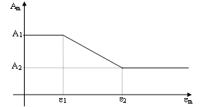
Strut Area 2 - A2
Introduced as percentage of A1, and which aims at accounting for the fact that due to cracking of the infill panel, the contact length between the frame and the infill decreases as the lateral and consequently the axial displacement increases, affecting thus the area of equivalent strut. It is assumed that the area varies linearly as function of the axial strain (see Figure below), with the two strains between which this variation takes place being defined as input parameters of the masonry strut hysteresis model.
Equivalent contact length - hz
Introduced as percentage of the vertical height of the panel, effectively yielding the distance between the internal and dummy nodes, and used so as to somehow take due account of the contact length between the frame and the infill panel. Reasonable results seem to be obtained for values of 1/3 to 1/2 of the actual contact length (z), defined by Stafford-Smith [1966] as equal to ![]() , where
, where ![]() is a dimensionless relative stiffness parameter computed by the Equation given below, in which Em is the Elastic Modulus of the masonry, tw is the thickness of the panel,
is a dimensionless relative stiffness parameter computed by the Equation given below, in which Em is the Elastic Modulus of the masonry, tw is the thickness of the panel, ![]() is the angle of the diagonal strut with respect to the beams, EcIc is the bending stiffness of the columns, and hw is the height of the infill panel.
is the angle of the diagonal strut with respect to the beams, EcIc is the bending stiffness of the columns, and hw is the height of the infill panel.
Horizontal and Vertical offsets - xoi and yoi
Introduced as percentage of the horizontal and vertical dimensions of the panel, and which obviously represent the reduction of the latter due to the depth of the frame members. In other words, these parameters provide the distance between the external corner nodes and the internal ones.
Proportion of stiffness assigned to shear - ![]()
Representing the proportion of the panel stiffness (computed internally by the program) that should be assigned to the shear spring (typically, a value ranging between 0.2 and 0.6 is adopted). In other words, the strut stiffness (KA) and the shear stiffness (KS) are computed as follows:
![]()
![]()
Specific weight - ![]()
Representing the volumetric weight of the panel (it is recalled that no section, hence no material, is assigned to this element, for which reason the self-weight must be defined here). Default value is 20 kN/m3.
In this element's dialog box it is also possible to define an element-specific damping, as opposed to the global damping described in here. To do so, users need simply to press the Damping button and then select the type of damping that better suits the element in question (users should refer to the Damping menu for a discussion on the different types of damping available and hints on which might the better options). Users are reminded also that damping defined at element level takes precedence over global damping, that is, the "globally-computed" damping matrix coefficients that are associated to the degrees-of-freedom of a given element will be replaced by coefficients that will have been calculated through the multiplication of the mass matrix of the element by a mass-proportional parameter, or through the multiplication of the element stiffness matrix by a stiffness-proportional parameter, or through the calculation of an element damping Rayleigh matrix.
Notes
- It is noted that this model (with its struts configuration) is capable of describing only the commonest of modes of failure, since a model that would account for all types of masonry failure would not be practical due to the appreciable level of complexity and uncertainty involved. Users are strongly advised to consult the publications of Crisafulli et al. [2000] and Smyrou et al. [2006] for further details on this model.
- Note that strength and stiffness of the infills are introduced after the application of the initial loads, so that the former do not resist to gravity loads (which are normally absorbed by the surrounding frame, erected first). If users wish their infills to resist gravity loads, then they should define the latter as non-initial loads.
- In very refined models, users may wish to introduce link elements between the frame and infill panel nodes, in order to taken into account the fact that the infills are commonly not rigidly connected to the surrounding frames.
- Users may also want to check for values of out-of-plane acceleration exceeding a certain threshold limit that may be inducing out-of-plane failure of the panel (deactivation of the element may then be set for the time corresponding to the attainment of such acceleration values).
- The presence of openings in infill panels constitutes an important uncertainty in the evaluation of the behaviour of infilled frames. Several researchers [e.g. Benjamin and Williams, 1958; Fiorato et al., 1970; Mallick and Garg, 1971; Liauw and Lee, 1977; Utku, 1980; Dawe and Young, 1985; Thiruvengadam, 1985; Giannakas et al., 1987; Papia, 1988; Dawe and Seah, 1989; Hamburger, 1993; Bertoldi et al., 1994; CEB, 1996; Mosalam et al., 1997; Gostic and Zarnic, 1999; De Sortis et al., 1999; Asteris, 2003] have investigated the influence that different configurations of openings (in terms of size and location) might have on strength and stiffness. Unfortunately, though somewhat understandably given the large number of variables and uncertainties involved, agreement on this topic has not yet been reached; the above-listed publications have all lead to diverse quantitative conclusions and recommendations. Users will therefore need to resort to their own engineering judgement and experience, coupled with a thorough consultation of the literature on this topic (a small percentage of it has been listed above), in order to decide on how the presence of openings in the structure being studied should be taken into account. As an expedite recommendation, we might perhaps suggest that the effect of openings on the response of an infilled frame can be pragmatically taken into account by reducing the value of the Strut Area (A1), and hence of the panel's stiffness, in proportion to the area of the opening with respect to the panel. That is, as shown by Smyrou et al. [2006], if a given infill panel features openings of 15% to 30% with respect to the area of the panel, good response predictions might be obtained by reducing the value of A1 (i.e. its stiffness) by a value that varies between 30% and 50%. As far as the strength of the infill panel is concerned, and given the extremely varied nature of the observations made on this issue by past researchers, we would perhaps suggest that, in the absence of good evidence otherwise, users should not change its value to take into account the presence of standard openings (i.e. openings that are not larger than 30% of the area of the infill panel).
- Users are also warmly advised to read the publication of Celarec and Dolšek [2012] in which the effects of masonry infills on the shear demand and failure of columns, for the case when reinforced concrete frames with such infills are modelled by means of simplified nonlinear models that are not capable of the direct simulation of these effects, have been investigated.