Nonlinear link elements - NLlink
These are the 3D link elements with uncoupled axial, shear and moment actions that can be used to model, for instance, pinned or flexible beam-column connections, structural gapping/pounding, energy dissipating devices, bridge bearings, inclined supports, base isolation, foundation flexibility, and so on.
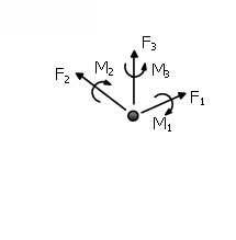
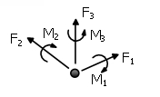
The link elements connect two initially coincident structural nodes and require the definition of an independent force-displacement (or moment-rotation) response curve for each of its local six degrees-of-freedom (F1, F2, F3, M1, M2, M3), indicated below.
Currently, twenty nine response curves are selectable within the Element Class dialog box, whenever a nonlinear link element type is selected.
- Linear symmetric curve - lin_sym
- Linear asymmetric curve - lin_asm
- Bilinear symmetric curve - bl_sym
- Bilinear asymmetric curve - bl_asm
- Bilinear kinematic hardening curve - bl_kin
- Trilinear symmetric curve - trl_sym
- Trilinear asymmetric curve - trl_asm
- Quadrilinear symmetric curve - quad_sym
- Quadrilinear asymmetric curve - quad_asm
- Pinched asymmetric curve - pinched_asm
- Modified Ibarra-Medina-Krawinkler Deterioration curve with Bilinear Hysteretic Response – MIMK_bilin
- Modified Ibarra-Medina-Krawinkler Deterioration Model with Peak-Oriented Hysteretic Response – MIMK_peak
- Modified Ibarra-Medina-Krawinkler Deterioration Model with Pinched Hysteretic Response – MIMK_Pinched
- Nonlinear elastic curve - nlin_el
- Plastic curve - plst
- Simplified bilinear Takeda curve - Takeda
- Asymmetric bilinear Takeda curve - Takeda_asm
- Ramberg Osgood curve - Ramberg Osgood
- Modified Richard-Abbott curve - Richard Abbott
- Soil-structure interaction curve - ssi_py
- Gap-hook curve - gap_hk
- Multi-linear curve - multi_lin
- Smooth curve - smooth
- Viscous Damper – vsc_dmp
- Bouc Wen Curve – Bouc_Wen
- Elastic – Perfectly plastic Gap Material - gap_elpl
- Impact response curve – pound_hz
- Self Centering Brace - scb
- Generic Hysteretic Curve – gen_hyst
In the Nonlinear Link element's dialog box it is also possible to define an element-specific damping, as opposed to the global damping described in here. To do so, users need simply to press the Damping button and then select the type of damping that better suits the element in question (users should refer to the Damping menu for a discussion on the different types of damping available and hints on which might the better options). Users are reminded also that damping defined at element level takes precedence over global damping, that is, the "globally-computed" damping matrix coefficients that are associated to the degrees-of-freedom of a given element will be replaced by coefficients that will have been calculated through the multiplication of the mass matrix of the element by a mass-proportional parameter, or through the multiplication of the element stiffness matrix by a stiffness-proportional parameter, or through the calculation of an element damping Rayleigh matrix. This facility is typically used here to model radiation damping in soil-structure interaction springs (featuring varied force-displacement rules, such as ssi_py or any other response curve), thus avoiding the need for introducing parallel dashpt elements.
Notes
- Only the response curves that have been previously activated in the Constitutive Model tab window (Tools > Project Settings > Constitutive Model) can be selected from the drop-down menu and associated to a nonlinear link element.
- When a nonlinear link element is introduced between two initially coincident nodes, a force-displacement relationship must compulsorily be defined for all six degrees-of-freedom, including those for which the response of the two nodes is identical. The latter are usually modelled by the adoption of linear response curves with very large stiffness values, so as to guarantee no relative displacement between the two nodes in that particular degree-of-freedom. The very large value to be adopted in such cases depends very much on the type of the analysis being carried out and on the order of magnitude of results being obtained. Too low a value will not reproduce infinitely stiff connection conditions, whilst a value that is too large may lead too numerical difficulties, especially when a force-based convergence criterion is adopted. Usually, and as a rule of thumb, users should consider a stiffness value that is 100 to 250 times larger than that of adjacent elements, noting however that only a sensitivity study will permit the determination of the optimum value.
- On some analyses, the adoption of K0=0 to model pinned joint conditions may lead to difficulties in getting the analysis to converge. This usually can be easily solved by the adoption a non-zero but still small value of stiffness (e.g. 0.001). Should the user wish to optimise the model (i.e. find the smallest possible stiffness value that will not give rise to accentuated numerical difficulties), then a sensitivity study ran on a case-by-case basis is highly recommended.
- In previous releases of SeismoStruct, link elements featuring a lin_sym response curve were typically employed to model pinned joints (zero stiffness) and/or Constraints. However, users may now use the Equal DOF facility (see Constraints) to achieve the same objective; e.g. a pin/hinge may be modelled by introducing an 'Equal DOF' constrain defined for translation degrees-of-freedom only.
- If Rayleigh damping is defined at element level, using varied coefficients from one element to the other, or with respect to those employed in the global damping settings, then non-classical Rayleigh damping is being modelled, since classic Rayleigh damping requires uniform damping definition.
- Damping is here typically coupled with link elements for the introduction of Soil-Structure Interaction springs adequate for dynamic analysis (see also ssi_py response curve).
Local Axes and Output Notation