Constraints
The different constraining conditions of the structure are defined in the Constraints module, where the constraint type, the associated master node, the restrained DOFs and the slave nodes are identified. As in all other modules, the user is capable of adding new conditions (also in the graphical input mode) and removing or editing existing ones (see module editing functions). In addition, however, Incrementation facility is available.
As in the case of elements, constraint incrementation enables the automatic generation of new constraints through "repetition" of existing ones. It functions in very much the same manner as the automatic generation of elements, with the difference that in this case only the names of the nodes (master and slave) are incremented. This facility obviously requires that node names respect the number (e.g. 111) or word+number (e.g. n111) formats.
Three different constraint types are available in SeismoStruct, which are Rigid Link, Rigid Diaphragm and Equal DOF. In what follows, an overview of each type is given.
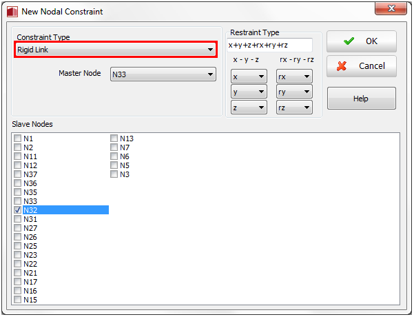
Rigid Link
Constrain certain degrees-of-freedom of slave nodes to a master node, by means of a rigid link. In other words, the rotations of the slave node are equal to the rotations of the master node, whilst the translations of the former are computed assuming a rigid lever-arm connection with the latter. Both master and slave nodes need to be defined for this constraint type, and the degrees-of-freedom to be slaved to the master node (restraining conditions) have to be assigned.
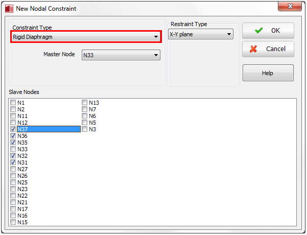
Rigid Diaphragm
Constrain certain degrees-of-freedom of slave nodes to a master node, by the use of rigid planes (i.e. all constrained nodes will rotate/displace in a given plane maintaining their relative position unvaried, as if they were all connected by rigid lever-arms). As for the previous constraint type, both master and slave nodes need to be defined, with the master node typically corresponding to the baricentre of the diaphragm. Moreover the restraining conditions, in terms of rigid plane connections (X-Y, X-Z and Y-Z plane), need also to be assigned.
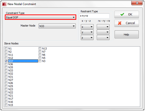
Equal DOF
Constrain certain degrees-of-freedom of slave nodes to a master node. Contrary to the Rigid Link constraint, here all constrained dofs (rotations and translations) of master and slave nodes feature the exact same value (i.e. no rigid lever-arm connection exists between them). Both master and slave nodes need to be defined for this constraint type, and the degrees-of-freedom to be slaved to the master node (restraining conditions) have to be assigned.
Notes
- In general, the diaphragm master node location should correspond to the centre of mass of each floor (it is noted that the location of slab master nodes in Wizard-created 3D models is merely demonstrative and not necessarily correct).
- It is noted that constraining all the nodes of a given floor level to a rigid diaphragm may lead to an artificial stiffening/strengthening of the beams, since the latter become prevented from deforming axially (it is recalled that unrestrained nonlinear fibre elements subjected to flexure will deform axially, since the neutral axis is not at the section's baricentre). Users are therefore advised to use great care in the employment of Rigid Diaphragm constraints, carefully selecting the floor nodes that are to be constrained.
- The application of displacement loads to nodes constrained to displace together may lead to convergence problems (because the applied displacements may be in contrast with the enforced constraint). Amongst many other modelling scenarios, this is particularly relevant when carrying out displacement-based Adaptive Pushover on a 3D model with displacement loads distributed throughout the floor (in such cases either the diaphragm should be eliminated or the displacement loads applied only on the sides of the floor).
- In previous releases of SeismoStruct, link elements featuring a lin_sym response curve were typically employed to model pinned joints (zero stiffness) and/or Constraints. However, users may now use the Equal DOF facility of this Constrain module to achieve the same objective; e.g. a pin/hinge may be modelled by introducing an 'Equal DOF' constrain defined for translation degrees-of-freedom only.
- It is noted that, when only two nodes are concerned, from a Finite Elements programming point of view, master and slave nodes are identical; both are "simply" two nodes connected between them. Do refer to the literature for further discussions on this topic [e.g. Cook et al., 1989; Felippa, 2004].