Global and local axes systems
In SeismoStruct, a fixed x-y-z global axis system is in place, used to define length (x), depth (y) and height (z) of all structural models. In addition, and being a 3D modelling program, SeismoStruct requires also that local 1-2-3 coordinate systems are assigned to all structural elements, so that their orientation in space is known. By convention, local direction (1) refers to the chord axis of the element, whilst axes (2) and (3) define the plane of the cross-section and its orientation. Although there are no constraints imposed on the definition of local axes (2) and (3), it is common for users to associate axis (2) to the "weak direction" of the member and to link axis (3) to the "strong direction" of the element, as illustrated below, where a beam is schematically represented. This is the convention also adopted in the illustrative drawings employed in the description of SeismoStruct's sections.
Whilst the orientation of local vector (1) results unambiguously characterised by the line joining the two end-nodes of the element (positive direction is that going from node n1 to node n2), an 'orientation object' is required in order to fully describe the orientation of the two other remaining local axes, and thus that of the cross-section. From the software version 6 the element's orientation may be achieved through two different ways:
- by defining a rotation angle (default option), which is set equal to 0 by default (models built with the Wizard facility follow this rule), or
- by defining additional nodes, called 'orientation node'. If the 'default' object is selected, the element's orientation is automatically computed by the program, otherwise it will depend on the position of the selected node.
The orientation node allows to define the plane (1-3) in which vector (3) lays in, its direction (perpendicular to axis (1)) and orientation (pointing towards n3), as shown below. Local vector (2) was then automatically obtained through the cross-product of vectors (1) and (3), with positive direction following the so-called right-hand rule.
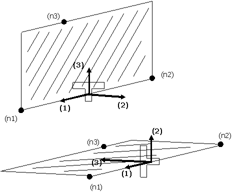
The vast majority of structures modelled in SeismoStruct are defined in plane frames and feature vertical elements (e.g. rectangular columns, walls) with symmetrical cross-sections and horizontal T-beams that are not symmetrical around their (2) axis. Hence, the selection of the 'default' object as a 'third node' can be very advantageous.
Note: In general, the rotation angle equal to 0 means that the axis (3) is vertical. The vertical elements (axis (1) is vertical) are a special case, where angle = 0 means that the axis (3) is along the X-direction.