Linear link elements - linlink
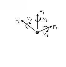
These are the 3D link elements with uncoupled axial, shear and moment actions. All six local Degrees of Freedom of the element (F1, F2, F3, M1, M2, M3) follow a linear behaviour. As a result the user only needs to define the elastic stiffness K for each of the six Local Degrees of Freedom.
The linear link elements connect two initially coincident structural nodes.
In the Link element's dialog box it is also possible to define an element-specific damping, as opposed to the global damping described in here. To do so, users need simply to press the Damping button and then select the type of damping that better suits the element in question (users should refer to the Damping menu for a discussion on the different types of damping available and hints on which might the better options). Users are reminded also that damping defined at element level takes precedence over global damping, that is, the "globally-computed" damping matrix coefficients that are associated to the degrees-of-freedom of a given element will be replaced by coefficients that will have been calculated through the multiplication of the mass matrix of the element by a mass-proportional parameter, or through the multiplication of the element stiffness matrix by a stiffness-proportional parameter, or through the calculation of an element damping Rayleigh matrix. This facility is typically used here to model radiation damping in soil-structure interaction springs (featuring varied force-displacement rules, such as ssi_py or any other response curve), thus avoiding the need for introducing parallel dashpt elements.
Local Axes and Output Notation