Inelastic masonry frame element – masonry
This element is combination of a 3D, force-based, plastic hinge element type employed in modelling mainly the bending behaviour of the masonry member (herein mentioned as the ‘internal sub-element’) with two links at the two edges that are employed to simulate the shear behaviour of the member (herein referred to as the ‘external links’ or the ‘link sub-elements’). The internal sub-element and the external links are connected in series, ensuring equilibrium in bending moment and shear force. The only ‘active’ degrees-of-freedom of the link sub-elements are the two translational ones in the shear directions (in-plane and out-of-plane), whilst the other four DOFs (axial and 3 rotational) remain perfectly rigid links. Both masonry walls and spandrels can be accurately modelled with such configuration.
The shear DOFs of the link sub-elements feature a hysteretic curve that is based on SeismoStruct’s built-in MIMK_pinched nonlinear curve (Modified Ibarra-Medina-Krawinkler deterioration curve with bilinear hysteretic rules and pinching), according to a phenomenological law that describes the shear behaviour of the entire member. Simultaneously, in the internal sub-element the fiber‐section modelling allows for a relatively accurate description of the coupled axial‐flexural behaviour. The sectional stress-strain state is obtained through the integration of the nonlinear uniaxial material response of the individual fibres, in which the section has been subdivided, fully accounting for the spread of inelasticity along the member length and across the section depth (as described in the Material inelasticitysection).
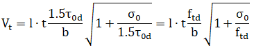
The determination of the shear strength of the member is crucial in the model accuracy, and is automatically carried out by the model, based on the masonry material properties, the dimensions of the member, and the selected Structural Code. The following expressions are employed for the calculation of the member shear capacity (it is noted that different equations are employed in the different Standards).
- In Eurcode 8, the failure mechanism of bed joint sliding is employed:

- In ASCE 41-23 and for unreinforced masonry URM walls, the lower value of the bed-joint sliding strength and the diagonal tension strength is used, according to the following expressions:


- In ASCE 41-23 and for unreinforced masonry URM spandrels, the lower value of the bed-joint strength and the diagonal tension strength is used, according to the following expressions:


- In ASCE 41-23 and for masonry walls or spandrels with reinforcement, the following expression is employed:

- In NTC-18 and for unreinforced masonry URM, different expressions are used for the different material types: (i) in masonry with blocks the Mohr-Coulomb criterion is employed, (ii) in masonry with bricks or regular stones, the strength assumes the lower value of the Turnšek-Čačovič and the Mann-Müller criteria and (iii) for masonry with irregular stones the Turnšek-Čačovič expression is employed.
Mohr-Coulomb (§7.8.2.2.2 NTC2018 and §6.2 EC6):

Turnšek-Čačovič (§C8.7.1.3.1.1 CircolareNTC2018):
Mann-Müller (§C8.7.1.3.1.1 Circolare NTC2018):

- In NTC-18 and for reinforced masonry RM, the shear capacity is calculated according to §7.8.3.2.2 NTC2018:


Note: For the checks according to KANEPE the expressions of EC8 are employed. Similarly, with TBDY the ASCE 41 equations are used. For a complete description of the employed expressions in each Standard, users may refer to the Appendices H1 to H6.
Two special masonry material models may be used with the masonry element type, mas_par and mas_tl. The former is based on the con_ma concrete material model, whilst the latter is a simpler multi-linear model with degradation and residual strength. Both models feature parameters, such as the compressive, the shear and the tensile strength, which are employed in the determination of the member shear strength. Similarly, there are two masonry specific section types in SeismoStruct, one for walls mws, and one for spandrels mss. Both unreinforced URM and reinforced RM masonry members can be effectively be modelled with the proposed features.
Note: The masonry element type can only be used with the mas_par and the mas_tl material models. Similarly, only the special masonry section types mws and mss can be employed. The reason for this, is that these can store parameters that are used for the automatic calculation of the member shear strength.
Users may choose whether to calculate the masonry shear strength (i) only at the initial step, (ii) at all the steps until yielding in shear or (iii) at every step, i.e. even after reaching the peak member capacity. The default option is the second, that is to update the shear strength until yield, which is the best combination of accuracy and stability, since updating the shear strength in the descending branch of the capacity curve may lead to convergence difficulties without significantly improving the accuracy of the solution.
The parameters required for the full definition of the element properties are the following (see figure above):
- The number of section fibres used in equilibrium computations carried out at each of the integration sections of the internal sub-element.
- The elastic stiffness reduction a is the reduction of the elastic uncracked stiffness of the shear force-deformation curve that is employed in the calculations
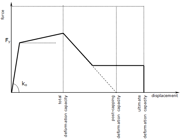
- The total shear deformation capacity, which is the ultimate deformation capacity of the member dtot=dyield+dplastic. It is noted that the deformation at yield dyield is directly calculated by the program from the elastic shear stiffness and the yield strength.
- The post-capping shear deformation capacity: this is the deformation level, at which the extrapolation of the descending branch of the shear force-deformation curve reaches the zero axis.
- The ultimate shear deformation capacity: this is the deformation level, after which there is no residual strength
- The residual shear strength ratio is the ratio between the maximum strength (at the total deformation capacity level) and the residual strength
- The shear deformation hardening ratio is the ratio between the elastic and the plastic branches of the shear force-deformation curve
- The cyclic deterioration parameters for the shear strength and stiffness are the following three parameters: (i) the cyclic deterioration parameter for strength deterioration, and accelerated reloading deterioration – Λs, Λα (ii) the cyclic deterioration parameter for unloading stiffness deterioration – ΛK, and (iii) the cyclic deterioration parameter for post-capping strength deterioration– Λc. For all parameters, the smaller the factor, the larger the imposed deterioration on the curve, however note that a zero value leads to no deterioration. For a complete description of the parameters refer to the documentation of the MIMK_pinched curve
- Ratio between force at start of reloading to the force corresponding to the maximum experienced deformation for positive and negative loading directions
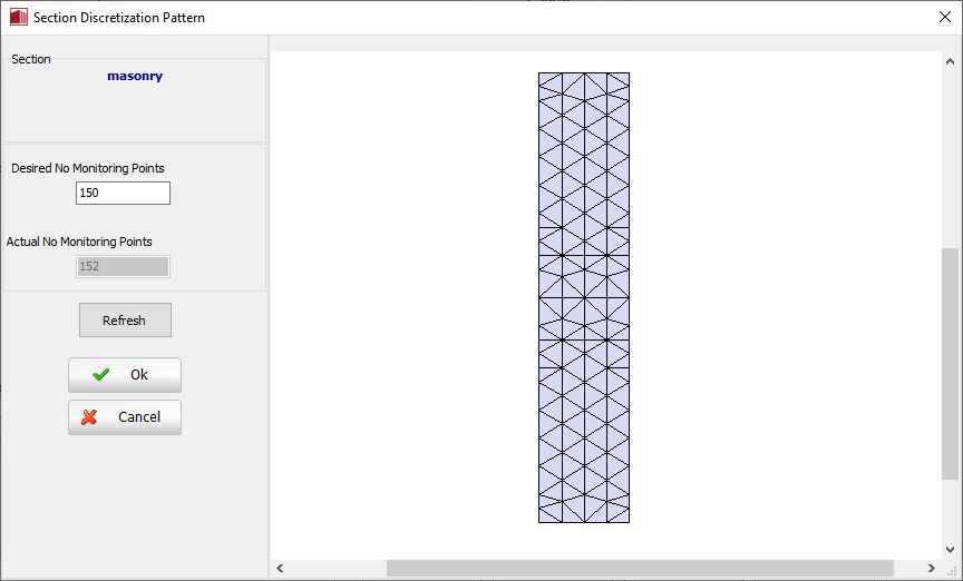
Regarding the section fibres, the ideal number, sufficient to guarantee an adequate reproduction of the stress-strain distribution across the element's cross-section, varies with the shape and material characteristics of the latter, and the degree of inelasticity to which the element will be forced to. As a crude rule of thumb, users may consider that usually 100 fibres should be adequate.
In the Section Discretization Pattern dialog box the software provides the desired and the actual (after the section discretization has been performed, employing triangulation procedures) number of monitoring points that will be employed in the analysis. By clicking on the Refresh button it is possible to update the view of the section discretization.
Similarly to the inelastic frame element types, instead of discretizing the elements to represent the changes in reinforcement details, it is possible to use one single element per member and then define multiple sections within it. It is noted that these sections may differ only in the reinforcement (i.e. section type, dimensions and materials have to be the same).
In this element's dialog box it is also possible to define an element-specific damping, as opposed to the global damping described in here. To do so, users need simply to press the Damping button and then select the type of damping that better suits the element in question (users should refer to the Damping menu for a discussion on the different types of damping available and hints on which might the better options). Users are reminded also that damping defined at element level takes precedence over global damping, that is, the "globally-computed" damping matrix coefficients that are associated to the degrees-of-freedom of a given element will be replaced by coefficients that will have been calculated through the multiplication of the mass matrix of the element by a mass-proportional parameter, or through the multiplication of the element stiffness matrix by a stiffness-proportional parameter, or through the calculation of an element damping Rayleigh matrix.
Note: If Rayleigh damping is defined at element level, using varied coefficients from one element to the other, or with respect to those employed in the global damping settings, then non-classical Rayleigh damping is being modelled, classing Rayleigh damping requires uniform damping definition.
Local Axes and Output Notation