Wizard
In order to facilitate the creation of frame/building models in SeismoStruct, a Wizard facility has been developed and introduced in the program. The Wizard dialog box is accessed from the main menu (File > Wizard...) or through the corresponding toolbar button ![]() .
.
Structural model and configuration
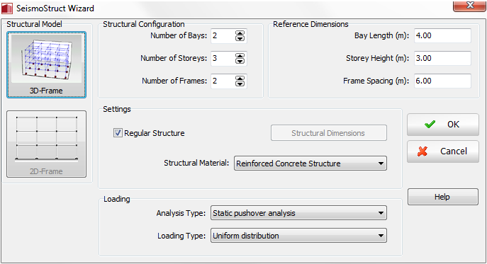
In order to create a building model using the Wizard, the user should first decide if he/she intends to create a 2D or 3D structure, after which the number of bays, storeys and frames can be assigned, together with the reference values for bay length, storey height and frame spacing. If the structure is regular (i.e. all bays have equal length, all storeys feature the same height and all frames are evenly spaced) then the reference dimensions become the actual ones. If, on the other hand, the structure is geometrically irregular, then the Regular Structure option should be unchecked so that the user can access the Structural Dimensions dialog box, where the actual bay lengths, storey heights and frame distances can be defined. By default, the reference dimensions are adopted.
Settings
Having defined the structural geometry, the user should now specify if the building is a reinforced concrete or steel structure. The Wizard generates structures employing the inelastic force-based plastic-hinge (infrmFBPH) elements type.
Note: If the user intends to adopt the other types of inelastic frame elements (infrmFB, infrmDBPH or infrmDB) rather than infrmFBPH, after the model's generation he/she may manually modify the element type in the Element Classes dialog box.
Each frame element generated through the Wizard facility is defined by 'structural' nodes at beam column joints. The names of these nodes are automatically created by following the n111 naming convention: all nodes have a name of the format: "n"+i+j+k, where i is the column number (starting from the left), j is the frame number (starting from the front) and k is the storey number (starting from the bottom/foundation) . For instance, n123 would refer to the node on the left column of the model (i=1), in the second frame (j=2) and at the third storey (k=3, third level of nodes ). Users should refer to the Nodes paragraph for further details on the nodes definition.
The orientation of the frame elements created using the Wizard facility is automatically defined by a rotation angle (by default equal to 0). Users should refer to here for further details on the element orientation.
Loadings
Finally, one of the nine Analysis Types available in SeismoStruct has to be selected, depending on which the following loads and restraining conditions are imposed on the structure:
- Eigenvalue analysis. Self-weight of the structure is considered. No loading is applied.
- Static analysis with non-variable loads. Permanent gravity loads are applied.
- Static pushover analysis. In addition to permanent gravity actions, Incremental loads, consisting of horizontal forces at each storey level, are also applied to the structure in the x-direction. The user has the possibility of choosing between two alternative load distributions (triangular or rectangular/uniform vector shapes) and of defining the nominal base-shear value (usually a value around the expected base shear capacity of the structure is used, though any given value is fine). Refer to the Loading Phases chapter for further details on pushover analysis loading characteristics.
- Adaptive static pushover analysis. In addition to permanent gravity actions, Incremental loads, consisting of horizontal displacements at each storey level, are also applied to the structure in the x-direction. Since the load distribution is automatically adapted by the program, the user needs only to specify the nominal displacement load to be used as reference value during the pushover procedure. Refer to the Adaptive Parameters chapter for further details on adaptive pushover analysis loading characteristics.
- Static time-history analysis. In addition to permanent gravity actions, Static Time-history Loads are applied to the top left hand side node of the building, in the x-direction. The user is asked to define the time-history curve (a pre-defined standard curve is in any case already provided) and corresponding curve multiplier (scaling factor).
- Dynamic time-history analysis. In addition to permanent gravity actions, Dynamic Time-history Loads are applied at the foundation nodes of the building, in the x-direction. The user is asked to define the time-history curve (usually an accelerogram) and corresponding curve multiplier (scaling factor). A number of exemplificative time-history curves (consisting of natural and artificial accelerograms) are pre-installed with the program and can be loaded into the program through the Select File command.
- Incremental dynamic analysis. In addition to permanent gravity actions, Dynamic Time-history Loads are applied at the foundation nodes of the building, in the x-direction. The user is first asked to define the incremental scaling factors (see IDA Parameters) and then needs to enter the time-history curve (usually an accelerogram) and corresponding curve multiplier (scaling factor). A number of exemplificative time-history curves (consisting of natural and artificial accelerograms) are pre-installed with the program and can be loaded into the program through the Select File command.
- Response spectrum analysis. In addition to permanent gravity actions, static loads are applied to the nodes of each storey level according to the modal shapes. Since the load distribution is automatically adapted by the program, the user needs only to specify the acceleration spectrum data and the loading combinations. A user defined spectrum can be introduced, or alternatively the time-history curves (consisting of natural and artificial accelerograms) pre-installed with the program can be used through the Select File command, and the program creates automatically the spectrum of the selected record.
- Buckling Analysis. Self-weight of the structure is considered. No loading is applied.
Notes
- If the user intends to adopt infrmDBPH elements rather than infrmFBPH, after the model's generation he/she may manually modify the element type in the Element Classes dialog box.
- When generating building models, the Wizard facility makes use of commonly encountered cross-sections dimensions and detailing, together with standard material properties. Evidently, after the completion of the model, the user may manually modify these input quantities so as to better represent the characteristics of the actual structure that he/she intends to analyse.
- The maximum building size that can be generated with the Wizard is 8 bays x 8 storeys x 9 frames (larger models would create problems with the automatic naming rules). Users who wish to create larger structures, however, can readily do so by employing the incrementation facilities for nodes, elements, constraints and loads.
- To define structural members that are subdivided in more than 4 elements, the model can be wizard-created with 1, 2 or 4 elements per member and then the Element Subdivision facility can be employed to further discretise the structural mesh.
- The Wizard facility automatically activates the calculation of the Target Displacement in the case of pushover analysis. For further details users may refer to the Target Displacement paragraph.
- The Wizard facility automatically generates Code-based Checks. For details on their definition users may refer here.
- The Wizard facility automatically generates Performance Criteria checks. For details on their definition users may refer here.