Beam (Plain and Jacketed)
New beams may be added with two clicks on the Building Modeller Main Window.
On the beam's Properties Window users can adapt the section’s dimensions either in the View/Modify Geometry window or by selecting one section from the predefined standard sections.
Inclined beams may be efficiently modelled by specifying the elevation differences of the two beam ends relatively to the general storey height. The heights of the columns that support the beam are then automatically adapted.
The material sets properties can be defined from the main window (Tools > Define Material Sets), through the corresponding toolbar  button, or through the Define Material Sets button within the member’s Properties Window. The required values for the definition of the materials properties depend on the type of the members, i.e. existing or new members. By default, there are two material schemes, one for the existing elements and one for the new ones.
In the beams sections module, additional permanent distributed load may also be assigned, which serves to define any load not associated to the self-weight of the structure (e.g. finishings, infills, variable loading, etc). Also loads can be defined by clicking on the More Loads button. Users can define uniform distributed forces along the length of the member in all three translational directions X, Y or Z, and forces or moments in any translational or rotational direction (X, Y, Z, RX, RY or RZ) at either of the two edges of the member (start or end). Additional permanent loads G’ (not associated with the self-weight of the structure), live Q and snow S loads may be applied, with the latter being applicable only to ASCE 41 and TBDY. By default all loads are equal to zero.
The longitudinal and transverse reinforcement may be assigned through the relevant reinforcement pattern controls. Different reinforcement patterns may be defined at the middle and at the two edges of the beam.
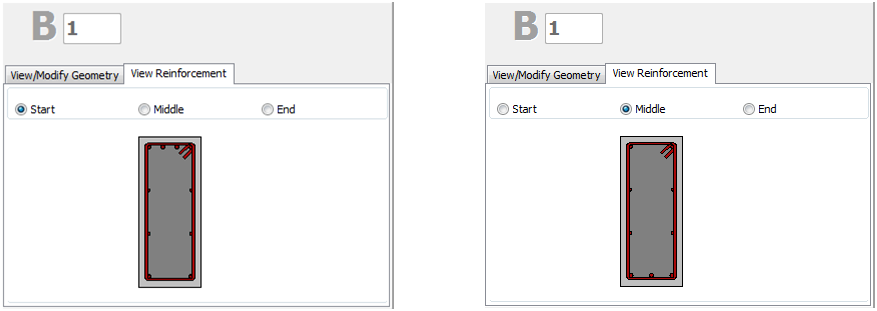
On the Properties Window users may choose the View Reinforcement display, where the reinforcement of the start, middle and end sections is shown (longitudinal and transverse), and may check for its correct assignment.
Jackets may be applied to the section in the Jacket area by selecting the jacket type, i.e. whether it is full jacketed, 3-sided or 1-sided jacket, and assigning the material set and the longitudinal and transverse reinforcement of the jacket.
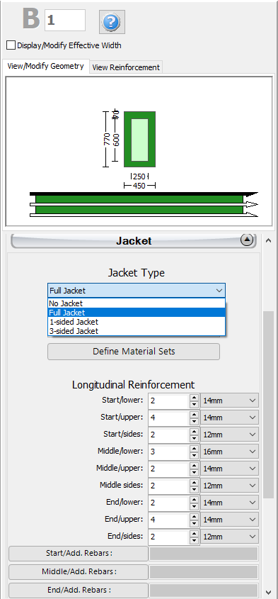
Adding single longitudinal reinforcement bars to the jacket can also be carried out through the corresponding Additional Rebars module, where additional reinforcement may be introduced graphically to both the existing and the new part of the section.
In the Advanced Modelling area, the code-based settings of the structural member can be defined through the Advanced Member Properties dialog box that opens from the corresponding button. The member’s Modelling Parameters may be also defined from the Modelling Parameters dialog box, accessed by the corresponding button. Finally, the insertion point (point of the section that corresponds to the location of the mouse click), and rotation of the section on plan view may be selected.
After defining all the section's properties, the new member may be added by outlining two points on the Main Window. The inserting line can lie at the centre or at either of the two sides of the beam; this can be determined by clicking on any of the three lines on the View/Modify Geometry window (the black line is the selected option).
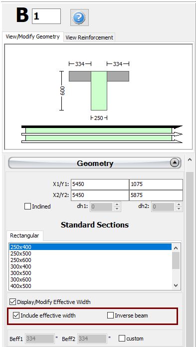
After the definition of the slabs, two additional options may appear on the Geometry area of the beams Properties Window: (i) select whether to include or not the beam's effective width in the calculations and (ii) select whether the beam is inverted or not. The effective width of the beam is automatically calculated by the program, but it can also be modified by the user.
For guidelines on how to insert a beam click here.
Notes
- In the case of beams being supported by the same column at different heights, the program automatically subdivides the column member, so that to simulate effectively the short column that is generated.
- When the section is jacketed, in the Advanced Member Properties module users should take decisions on the parameters, so as to account for the entire section, i.e. for both the existing and the new parts.