Insert Columns
A column may be inserted from the main menu (Insert >...) or through the corresponding toolbar buttons.
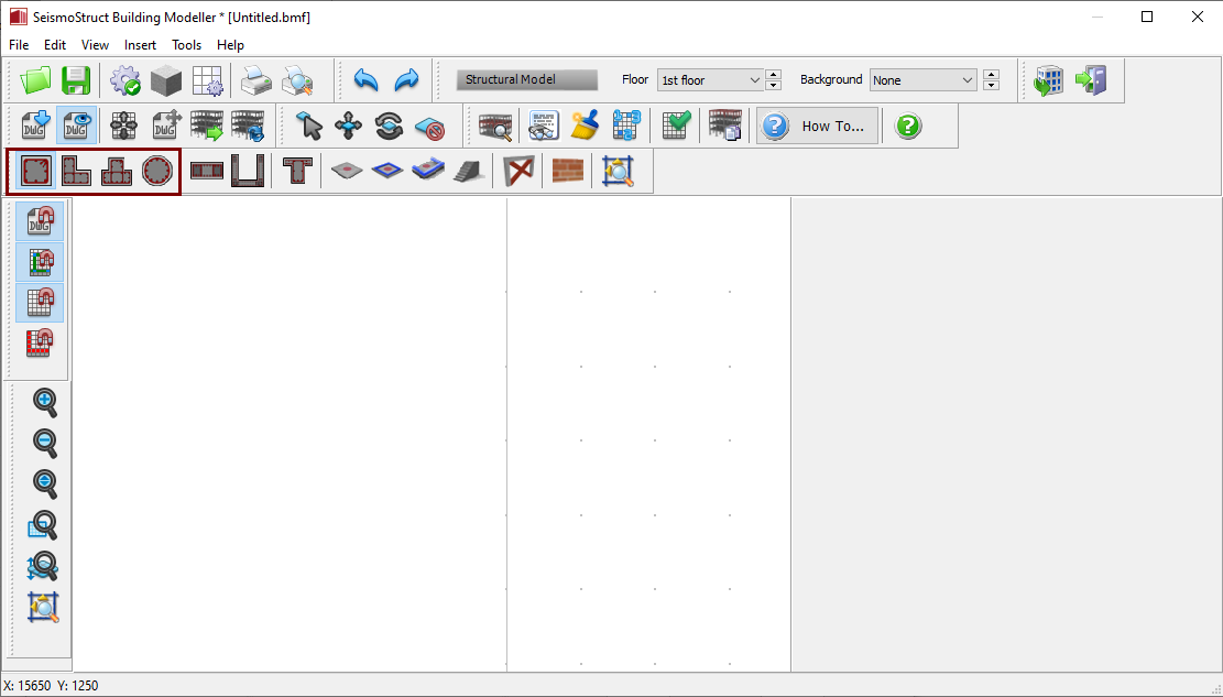
Once the required column is selected, its Properties Window appears on the right-hand side of the screen.
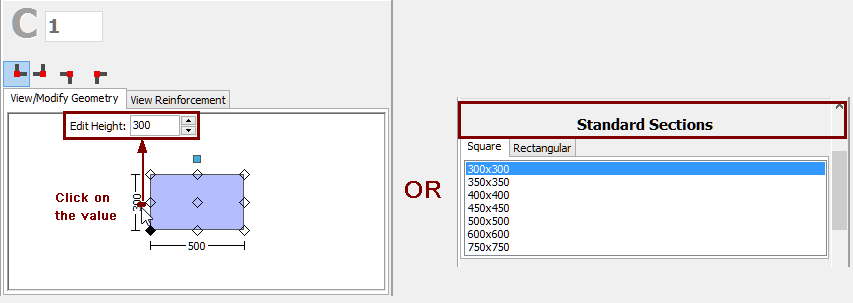
On the column's Properties Window users can adapt the section’s dimensions either in the View/Modify Geometry window or by selecting one section from the predefined standard sections.
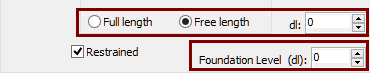
It is possible to define a column height different from the general storey height by selecting the 'Free length' radio button and assigning the value of the height difference. Further, it is possible to adapt the foundation level of columns at the ground floor, thus providing the possibility to the user to define buildings with varying foundation levels.
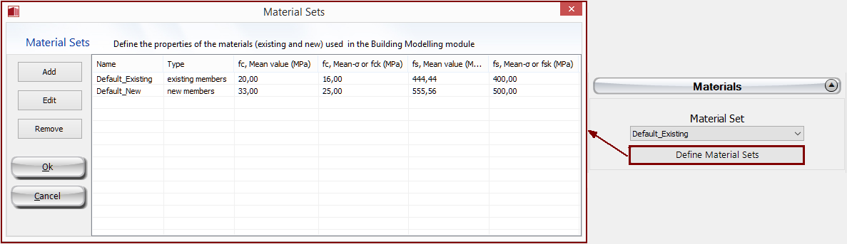
The
Material
Sets properties
can be defined from the main window (Tools
> Define Material Sets), through the corresponding toolbar
![]() button,
or through the Define Material Sets button within the member’s
Properties Window.
It is noted that in the jacketed columns the possibility
of defining different material sets for the internal (pre-existing)
and the jacket (new) concrete materials is available.
button,
or through the Define Material Sets button within the member’s
Properties Window.
It is noted that in the jacketed columns the possibility
of defining different material sets for the internal (pre-existing)
and the jacket (new) concrete materials is available.
The longitudinal and transverse reinforcement may be defined by editing the relevant reinforcement pattern controls. Adding single longitudinal reinforcement bars may also be carried out through the corresponding Additional Rebars module, where additional reinforcement may be introduced graphically.
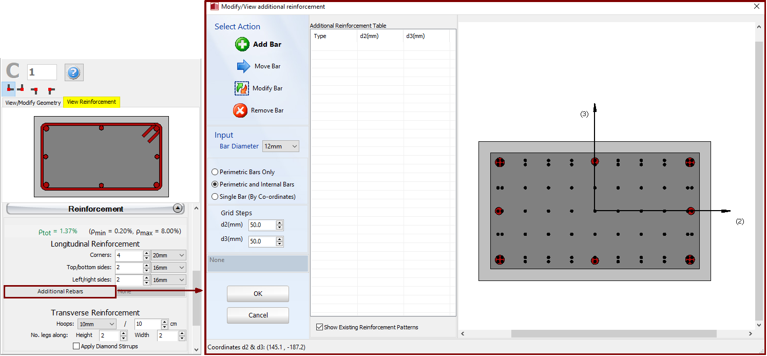
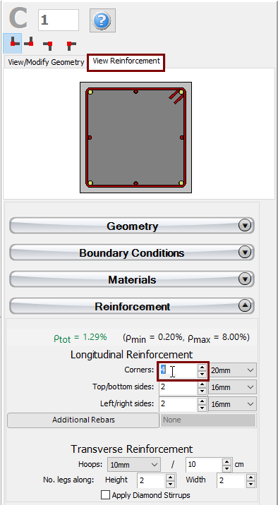
When editing the reinforcement patterns the program automatically switches to the View Reinforcement display, where the reinforcement (longitudinal and transverse) of the section is shown and users may check for its correct assignment.
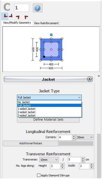
Jackets may be applied to the section in the Jacket area by selecting the jacket type, i.e. whether it is full jacketed, 1-sided, 2-sided or 3-sided jacket, and assigning the material set and the longitudinal and transverse reinforcement of the jacket.
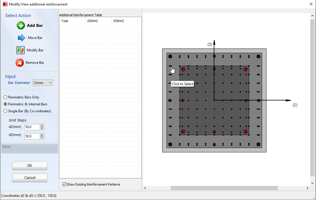
Adding single longitudinal reinforcement bars to the jacket can also be carried out through the corresponding Additional Rebars module, where additional reinforcement may be introduced graphically to both the existing and the new part of the section, as shown in the following figure:
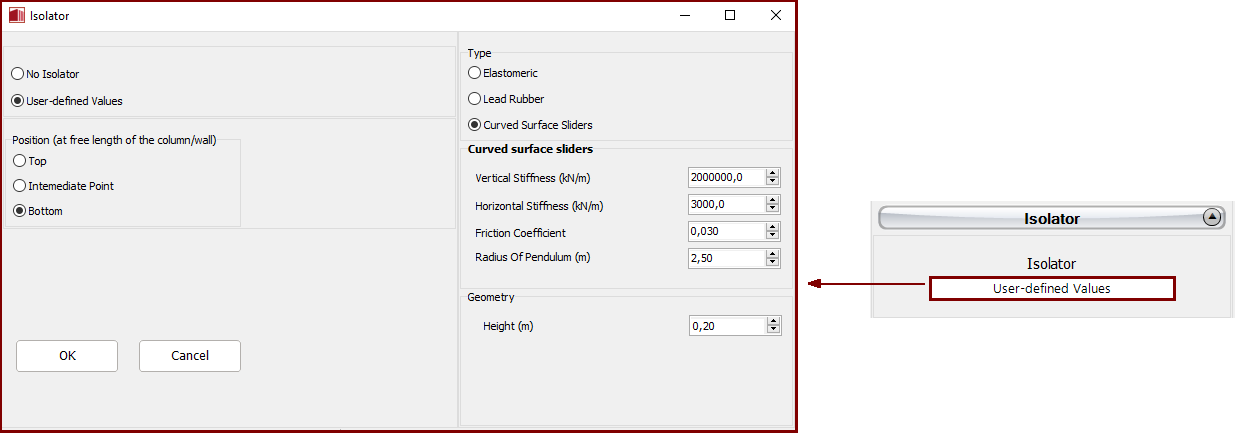
Isolators can also be added at different locations of the column. They are assigned through the Isolator module, where the users may select the geometry (location -bottom, top or intermediate point- and the height of the isolator), its type (elastomeric, lead rubber or curve surface slider) and the isolator parameters: the vertical and horizontal stiffnesses, and the shear yield strength and the strain hardening ratio (for elastomeric and lead rubber isolators, which are modelled as isolator1) or the friction coefficient and the radium of the pendulum (for curve surface sliders, which are modelled as isolator2).
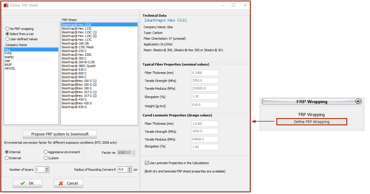
Further, FRP wraps may be assigned to columns through the FRP Wrapping module, where the users may select the FRP sheet from a list of the most commonly used products found in the market, or alternatively introduce user-defined values.
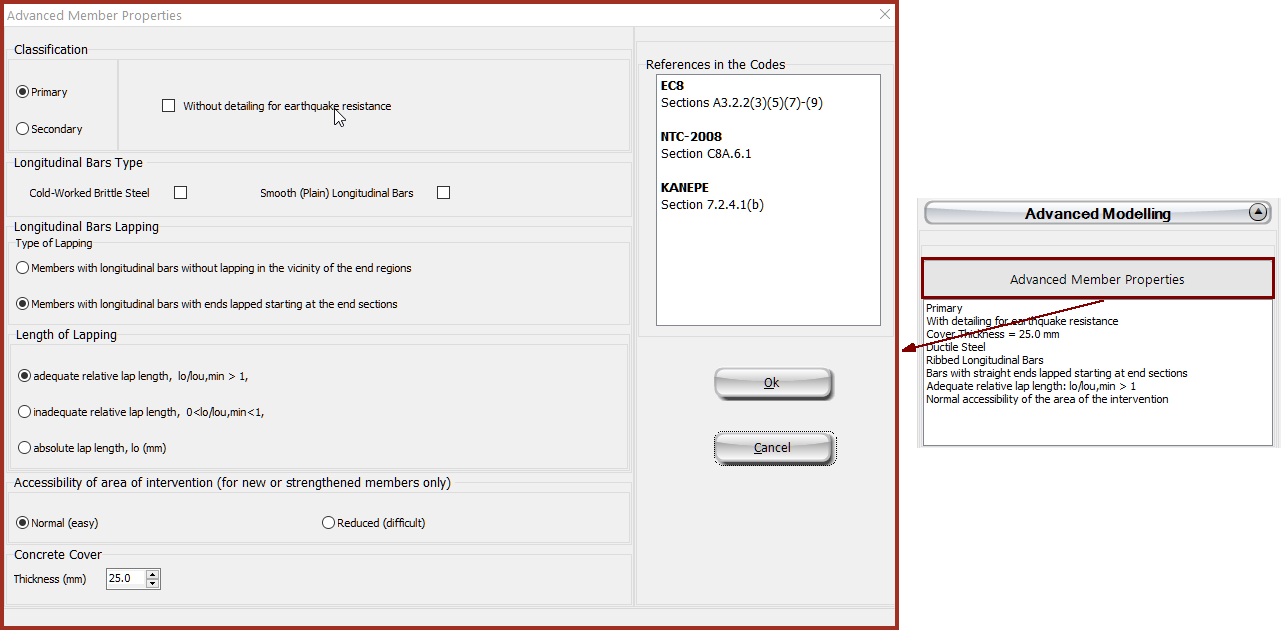
The code-based settings of the structural member can be defined through the Advanced Member Properties dialog box that opens from the corresponding button.
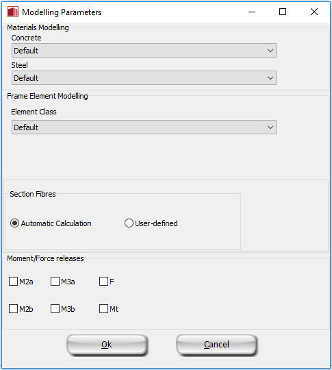
The modelling parameters of the structural member can also be defined through the Modelling Parameters dialog box that opens from the corresponding button.
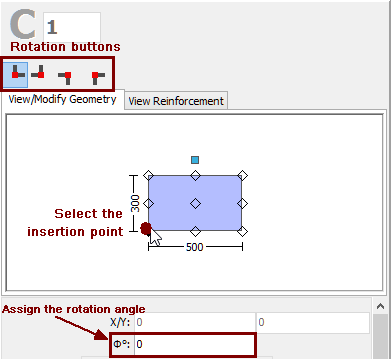
Finally, the insertion point (point of the section that corresponds to the location of the mouse click) may be chosen by clicking on the corner, middle or side points of the section's plot on the Properties Window, whereas the rotation of the column on plan-view can be changed by the 0o, 90o, 180o and 270o buttons or by assigning the proper angle on the corresponding of editbox of the Properties Window.
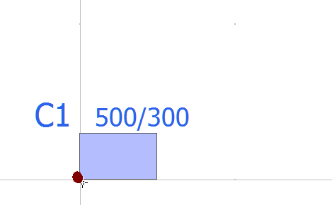
After defining all the section's properties, the new member may be added graphically with a simple mouse click on the building's plan view.
Note: When the section is jacketed, in the Advanced Member Properties module users should take decisions about the jacketed section’s properties, selecting the parameters so as to account for the entire section, i.e. for the both the existing and the new parts.