Insert Strip Footings
Strip Footings may be added from the main menu (Insert >
Insert Strip Footing) or the corresponding toolbar button ![]() .
.
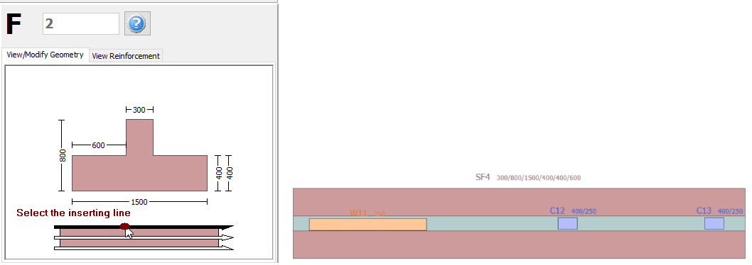
Once the strip footing is selected, its Properties Window appears on the right-hand side of the screen.
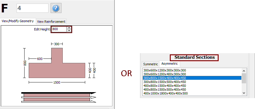
On the strip footing's Properties Window users can adapt the section’s dimensions either in the View/Modify Geometry window or by selecting one section from the predefined standard sections.
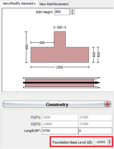
The base level of the strip foundation may be adapted relatively to the foundation level of the building, in order to define a different foundation level for a specific strip footing.
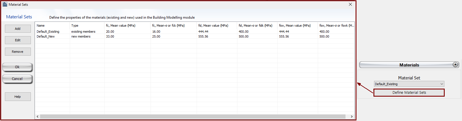
The Material
Sets properties can be defined from the main window (Tools
> Define Material Sets), through the corresponding toolbar
 button, or through
the Define Material Sets button within the member’s Properties
Window.
button, or through
the Define Material Sets button within the member’s Properties
Window.
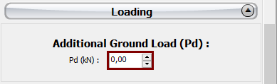
Additional distributed load may also be assigned in the Loading area, which will serve to define any load from the ground to the strip footing.
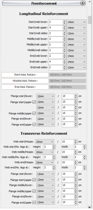
The longitudinal and transverse reinforcement may be assigned through the relevant reinforcement patterns. Different reinforcement patterns may be defined at the middle and at the two edges of the strip footing. Adding single longitudinal reinforcement bars may also be carried out through the corresponding Additional Rebars module, where additional reinforcement may be introduced graphically.
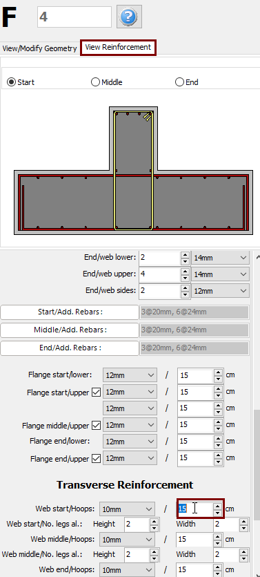
When editing the reinforcement patterns the program automatically switch to the View Reinforcement display, where the reinforcement (longitudinal and transverse) of the start, middle and end sections is shown and users may check for its correct assignment.
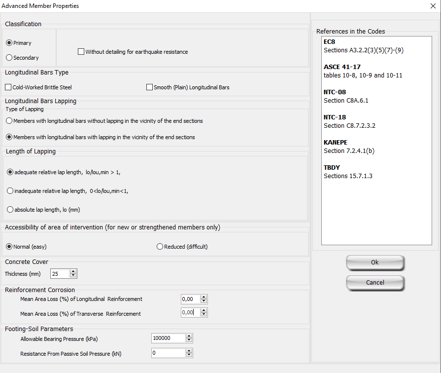
The code-based settings of the structural member can also be defined through the Advanced Member Properties dialog box that opens from the corresponding button.
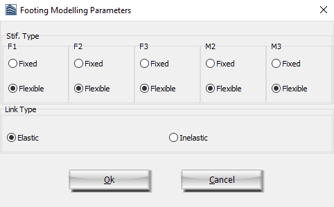
The modelling parameters of the structural member can also be defined through the Footing Modelling Parameters dialog box that opens from the corresponding button.
After defining all the section's properties, the new member may be inserted graphically with two mouse clicks on the building's plan view that outline the start and the end of the strip footing. The inserting line can lie at the centre or at either of the two sides of the strip footing; this can be determined by clicking on any of the three lines on the View/Modify Geometry window (the black line is the selected option).