Reinforced concrete rectangular wall section - rcrws
This is a section that can be adopted in the modelling of reinforced concrete walls of any shape. Rigid links/arms featuring half of the wall's width need to be used to connect the wall's frame element to adjacent structural members, in order for the rigid body motion of the wall, and its influence on such connected structural elements, to be adequately modelled. Users are warmly advised to read the work of Beyer et al. [2008] for further guidance on this topic, especially when interested in using this cross-section to model L- or U-shaped walls.
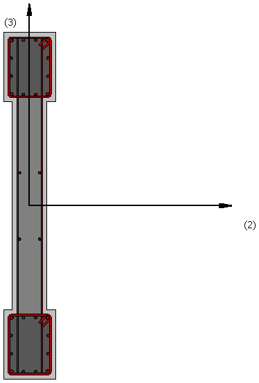
Materials and Dimensions
Three different materials can be defined; longitudinal reinforcement, transverse reinforcement, concrete.
The required dimensions are as follows:
- Wall width. The default value is 2m
- Thickness of section edges. The default value is 0.3 m
- Width of section edges. The default value is 0.4 m
- Thickness of section core. The default value is 0.2 m
- Cover Thickness. The default value is 0.025 m
Reinforcement
Longitudinal reinforcement bars can be defined in two different ways:
- by editing the reinforcement pattern;
- by entering the respective area and sectional coordinates (the latter being defined in the local coordinate system of the section).
Further, the transverse reinforcement may be specified, in terms of the stirrups' diameters and legs, as well as the distance between them. Diamond stirrups at the section's edges may be also added.
FRP Strengthening
FRP wraps may be assigned by selecting the FRP Wrap from a list of the most common products found in the internet, or by introducing user defined values.
Notes
- The confined concrete region is automatically computed by the program using the R/C cover thickness.
- All re-bars must be located within the confined concrete region.