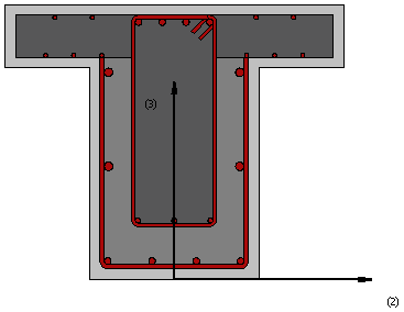
Reinforced concrete 3-side jacketed T-section – rcjts3
This is a section frequently adopted for the modelling of reinforced concrete beams, with T-, L- or rectangular shapes (to model the L-section it is necessary to define a null beam eccentricity, whilst to model the latter users should define identical values for slab and beam widths) that have been retrofitted in three sides by means of reinforced concrete jacketing (steel- or FRP-wrapping can be modelled using the existing RC sections). The possibility of defining different confinement levels for the internal (pre-existing) and the external (new) concrete materials is available.
Materials and Dimensions
Six different materials can be defined; external longitudinal reinforcement, internal longitudinal reinforcement, external transverse reinforcement, internal transverse reinforcement, concrete jacket, concrete core.
The required dimensions are as follows:
- External Beam height. The default value is 0.65 m
- External Beam width. The default value is 0.4 m
- Internal Beam height. The default value is 0.5 m
- Internal Beam width. The default value is 0.2 m
- Slab effective width. The default value is 0.8 m
- Slab 1 thickness. The default value is 0.15 m
- Slab 2 thickness. The default value is 0.15 m
- Beam eccentricity. The default value is 0.3 m
- Cover Thickness. The default value is 0.025 m
Reinforcement
Longitudinal reinforcement bars can be defined in two different ways:
- by editing the reinforcement pattern;
- by entering the respective area and sectional coordinates (the latter being defined in the local coordinate system of the section).
Further, the transverse reinforcement may be specified, in terms of the stirrups' diameters and legs, as well as the distance between them.
Important: Re-bar distance d3 is to be measured from the bottom of the section.
Notes
- The confined concrete region is automatically computed by the program using the R/C cover thickness.
- All re-bars must be located within the confined concrete region.