Strip Footings
New strip footings may be added with two clicks on the Building Modeller Main Window.
On the Properties Window that appears users can adapt the section’s dimensions in the View/Modify Geometry window, whereas its length is graphically defined with its insertion by specifying two points, start and end.
The base level of the strip foundation may be adapted relatively to the foundation level of the building, in order to define a different foundation level for a specific strip footing.
The material
sets properties
can be defined from the main window (Tools > Define Material
Sets), through the corresponding toolbar  button,
or through the Define Material Sets button within the member’s
Properties Window. The required values for the definition of the
materials properties depend on the type of the members, i.e. existing
or new members. By default, there are two material schemes, one
for the existing elements and one for the new ones.
button,
or through the Define Material Sets button within the member’s
Properties Window. The required values for the definition of the
materials properties depend on the type of the members, i.e. existing
or new members. By default, there are two material schemes, one
for the existing elements and one for the new ones.
Additional distributed load may also be assigned in the Loading area, which will serve to define any load from the ground to the strip footing.
Further, the longitudinal and transverse reinforcement may be defined by editing the relevant reinforcement pattern controls in the reinforcement area.
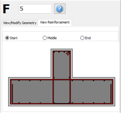
On the Properties Window users may choose between the View Reinforcement, where the reinforcement of the start, middle and end sections is displayed (longitudinal and transverse), and the View/Modify Geometry, where the section’s dimensions may be viewed and modified.
In the Advanced Modelling area, the code-based settings of the structural member can be defined through the Advanced Member Properties dialog box that opens from the corresponding button. The Footing Modelling Parameters may be also defined from the Modelling Parameters dialog box, accessed by the corresponding button.
For guidelines on how to insert a beam click here.