Connecting Beams
New connecting beams may be added with two clicks on the Building Modeller Main Window.
On the Properties Window that appears users can adapt the section’s dimensions either in the View/Modify Geometry window or by selecting one section from the predefined standard sections.
Inclined connecting beams may be efficiently modelled by specifying the elevation differences of the two connecting beam ends relatively to the foundation base level.
The material
sets properties
can be defined from the main window (Tools > Define Material
Sets), through the corresponding toolbar  button,
or through the Define Material Sets button within the member’s
Properties Window. The required values for the definition of the
materials properties depend on the type of the members, i.e. existing
or new members. By default, there are two material schemes, one
for the existing elements and one for the new ones.
button,
or through the Define Material Sets button within the member’s
Properties Window. The required values for the definition of the
materials properties depend on the type of the members, i.e. existing
or new members. By default, there are two material schemes, one
for the existing elements and one for the new ones.
In the connecting beams sections module, additional distributed load may also be assigned, which will serve to define any load from the ground to the connecting beam.
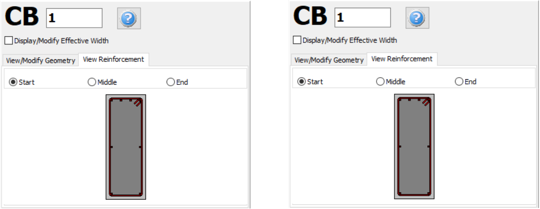
Further, the longitudinal and transverse reinforcement may be assigned through the relevant reinforcement pattern controls. Different reinforcement patterns may be defined at the middle and at the two edges of the beam.
On the Properties Window users may choose between the View Reinforcement, where the reinforcement of the start, middle and end sections is displayed (longitudinal and transverse), and the View/Modify Geometry, where the section’s dimensions may be viewed and modified.
In the Advanced Modelling area, the code-based settings of the structural member can be defined through the Advanced Member Properties dialog box that opens from the corresponding button. The member’s modelling parameters may be also defined from the Modelling Parameters dialog box, accessed by the corresponding button.
In a similar fashion to the beams, for connecting beam’s definition two points should be outlined on the Main Window. The inserting line can lie at the centre or at either of the two sides of the connecting beam; this can be determined by clicking on any of the three lines on the View/Modify Geometry (the black line is the selected option).
For guidelines on how to insert a connecting beam click here.