Building Modeller
A specially designed modeller facility has been developed and introduced in the program in order to facilitate the creation of building models. Currently, only reinforced concrete buildings can be created; in subsequent releases of the program steel and composite models will be also supported.
The
Building Modeller is accessed from the main menu (File
> Building Modeller...) or through the corresponding toolbar
button ![]() .
.
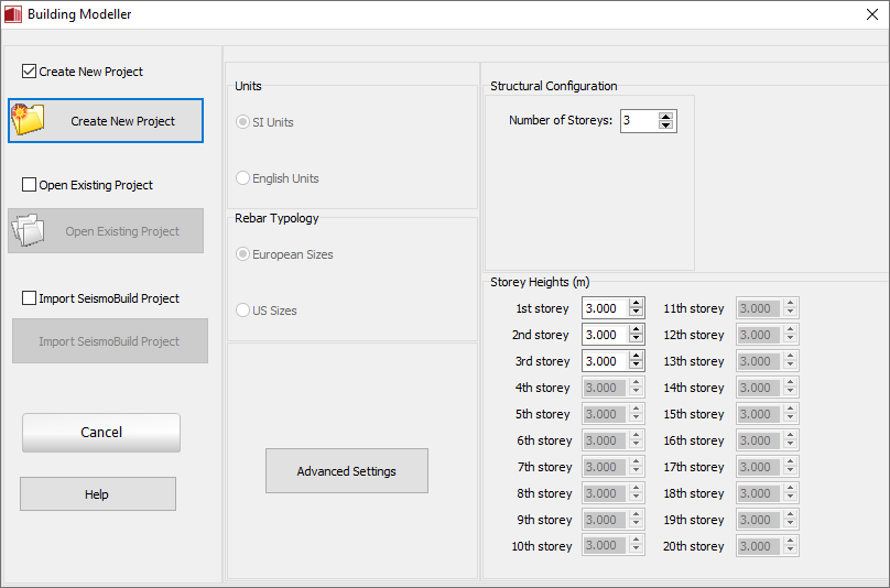
Basic settings and structural configuration
In order to create a building model using the Building Modeller, the number of storeys and their heights are defined; a number from 1 to 100 storeys, with different heights at each storey and the possibility of applying a common height to a range of storeys, may be selected. Up to three underground floors (basement storeys) and their heights may also be defined.
The Advanced settings of the project may be defined from the initialization screen of the Modeller or during its creation.
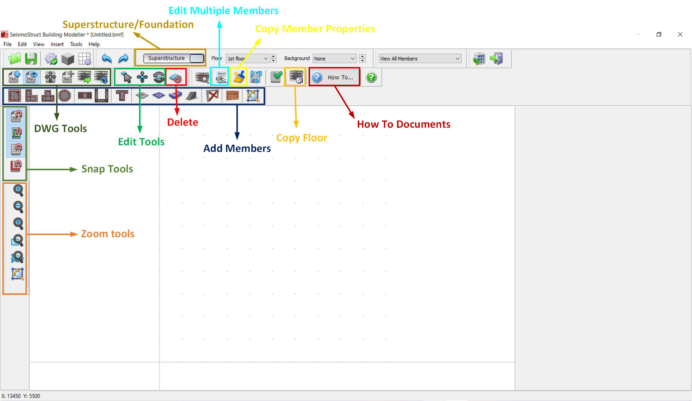
The possibility
of inserting a CAD drawing is offered from the main menu (File
> Import DWG...) or through the corresponding toolbar button
 .
Once the drawing is inserted the user is asked whether to move
the DWG/DXF file to 0,0, i.e. to the origin of the coordinates
system. Selecting Yes will move the bottom-left
edge of the drawing to the (0,0) coordinates, irrespective of
its initial CAD coordinates. Note that the axes origin can be
further moved to a different point that might be more suitable
with the
.
Once the drawing is inserted the user is asked whether to move
the DWG/DXF file to 0,0, i.e. to the origin of the coordinates
system. Selecting Yes will move the bottom-left
edge of the drawing to the (0,0) coordinates, irrespective of
its initial CAD coordinates. Note that the axes origin can be
further moved to a different point that might be more suitable
with the ![]() toolbar button. The option of moving the imported CAD
file is also available through the Move DWG () toolbar button or from the main menu
(View > Move DWG).
Further, through the toolbar button
toolbar button. The option of moving the imported CAD
file is also available through the Move DWG () toolbar button or from the main menu
(View > Move DWG).
Further, through the toolbar button ![]() the
option whether the CAD drawing will be visible or not is defined.
A number of useful corresponding
buttons are offered in order to easily insert and edit
structure's members, as well as execute a variety of other
functions. The created model can be saved as a Building
Modeller project to be opened and changed again in the future
or used to automatically create a new SeismoStruct
project. Users may also move the building in plan view
from the main menu (Tools
> Move Building) or from the corresponding toolbar button
by
either assigning the relative coordinares or by selecting the
base point and the second point graphically.
the
option whether the CAD drawing will be visible or not is defined.
A number of useful corresponding
buttons are offered in order to easily insert and edit
structure's members, as well as execute a variety of other
functions. The created model can be saved as a Building
Modeller project to be opened and changed again in the future
or used to automatically create a new SeismoStruct
project. Users may also move the building in plan view
from the main menu (Tools
> Move Building) or from the corresponding toolbar button
by
either assigning the relative coordinares or by selecting the
base point and the second point graphically.
Notes
- Different element types may be employed for the modelling of columns/beams and walls. For details on their definition users may refer to the Advanced settings of the Building Modeller.
- The Building Modeller facility automatically generates Performance Criteria checks. For details on their definition users may refer here.
- The Building Modeller facility automatically generates Code-based Checks. For details on their definition users may refer here.