Friction Pendulum Isolator/System – isolator 2
Isolator 2 Elements are 3D elements with zero length used to model the behaviour of single friction pendulum isolators used in Seismic Isolation Applications. Isolator 2 Elements have coupled plasticity properties for the two shear directions (axes 2 and 3 in the local coordinate system of the element) while they are characterised by linear elastic behaviour for the remaining four deformation types. The friction model described by Constantinou et al. [1999] is utilised for calculating the friction coefficient of the friction pendulum isolator sliding surface. The friction coefficient is calculated according to the following equation:

where ffast_1 and fslow_1 are the isolator friction coefficients at fast and slow velocities respectively, v is the isolator velocity and rate_1 is the rate controlling the transition from low to high velocities.
The Isolator 2 element behaves elastically in the shear directions, with a stiffness equal to the elastic stiffness provided by the user, until the yielding limit defined by the yield strength which is calculated according to the following equation
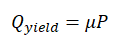
where P is the total vertical load on the isolator. Plastic deformations after the yielding point are computed using a Return-Mapping Algorithm as described for hardening models by Simo and Hughes [1998]. The post-yielding stiffness is equal to P/R where R is the radius of curvature of the friction pendulum and P is the total vertical load on the isolator.
Fourteen parameters are needed in order to describe the isolator 2 element behaviour:
Elastic Stiffness in the axial (local axis 1) direction -
K_axial
Linear elastic response of the isolator is considered in the axial
direction
Elastic Stiffness in the shear (local axis 2 and 3) directions - K_shear_1, K_shear_2
Elastic
Stiffnesses in the torsional and rotational degrees of freedom
- Ktorsional, Krot1, Krot2
Linear elastic response of the isolator is considered in the torsional
and rotational degrees of freedom.
Isolator friction coefficient at slow velocities – fslow_1, fslow_2
Isolator friction coefficient at fast velocities – ffast_1, ffast_2
Inverse of characteristic sliding velocities – rate_1, rate_2
curvature radii of the friction pendulum – radius_1, radius_2
In this element's dialog box it is also possible to define an element-specific damping, as opposed to the global damping described in here. To do so, users need simply to press the Damping button and then select the type of damping that better suits the element in question (users should refer to the Damping menu for a discussion on the different types of damping available and hints on which might the better options). Users are reminded also that damping defined at element level takes precedence over global damping, that is, the "globally-computed" damping matrix coefficients that are associated to the degrees-of-freedom of a given element will be replaced by coefficients that will have been calculated through the multiplication of the mass matrix of the element by a mass-proportional parameter, or through the multiplication of the element stiffness matrix by a stiffness-proportional parameter, or through the calculation of an element damping Rayleigh matrix.
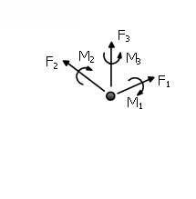
Local Axes and Output Notation