Tsunami parameters
With the Tsunami Nonlinear Analysis users can assess the capacity of a structure for Tsunami Loads within the framework of ASCE 7-16. The Tsunami Loads can be calculated either using the ASCE 7-16 relationships or the relationships proposed in Foster et al. [2017] while the analysis procedures are summarized in Petrone et al. [2017] and Baiguera et al. [2019]. More information on the Nonlinear Tsunami analysis can also be found in here.
For the Tsunami Nonlinear Analysis a number of parameters need to be defined and are summarized below:
Tsunami Force Calculation Method
The user can select whether the Total Tsunami Force at each step is to be calculated using
1. ASCE 7-16 Method: Utilizing the relationship 6.1-2 of the 6.10.2.1 paragraph of ASCE 7-16 (ASCE 7-16 chapter 6).
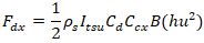
Where Fdx is the Total Tsunami Force, Itsu is the Tsunami Importance Factor, Cd is the drag Coefficient for the building (see Table 6.10-1 of ASCE 7-16 Chapter 6), h is the inundation depth, u is the flow velocity and Ccx is a coefficient given by equation 6.10-3 of ASCE 7-16 chapter 6 and B is the width of the structure affected by the Tsunami
2. Foster et al (2017) Method: Utilizing equation (1) from Petrone et al. [2017] relationships summarized in the work by Foster et al. [2017].
For Fr<Frc: 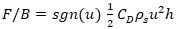
For Fr≥Frc: 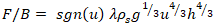
Where Fr is the Froude number, Frc is the Froude number threshold calculated according to the equations in Petrone et al. [2017], Cd is a drag coefficient, h and u are the inundation depth and flow velocity respectively, g is the acceleration of gravity, B is the width of the Tsunami affected area and λ is calculated using eq. (26) from Foster et al. [2017].
For each method a number of method-specific variables need to be defined namely:
Variables for the ASCE 7-16 method:
- Tsunami Importance Factor (Itsu): The Tsunami Importance Factor is taken according to the 6.8.3.2 paragraph of ASCE 7-16, Chapter 6.
- The Ccx factor calculated according to the equation 6.10.2 given in the paragraph 6.10.2.1 of the ASCE 7-16 Chapter 6.
Variables for the Foster et al. [2017] method:
- Blocking ratio: The blocking fraction b/w where w is the width of a channel of water flow and b is the width of an obstacle in the way of the channel, a model used in experimental works on Tsunami Modelling [Qi et al., 2014; Foster et al., 2017].
Tsunami force calculation and analysis variables
Type of Tsunami time series: The user can specify the type of depth and velocity time series to be used for the Tsunami modelling and the calculation of the Total Tsunami Force. The user can choose among the following options with each option needing its own variables to be specified.
- ASCE 7-16 Time-Series: Depth and Velocity time series of Figure 6.8-1 of the chapter 6 of ASCE 7-16. In order to fully define the time-series, the Maximum Inundation Depth (hmax) and Flow velocity (umax) of the Maximum Considered Tsunami should be defined
- ASCE 7-16 Time-Series up to Load Case 2: The Depth and Velocity time-series of ASCE 7-16 but up to the Load Case 2 point indicated in Figure 6.8-1 of ASCE 7-16 Chapter 6. The variables that need to be defined are again hmax and umax.
- Variable Depth/Constant Froude Number Time-Series option: The depth is increasing linearly from a minimum to a maximum depth while the velocity is calculated using a constant Froude number. The needed variables are the Minimum and Maximum Depth and the Constant Froude number
- Time-Series with max.depth = building height: This option creates the ASCE 7-16 depth/velocity time-series us to load case 2 and after Load Case 2 the depth continues to increase linearly until it reaches the building height. The hmax and umax need to be defined for the calculation of the ASCE depth and Velocity time-series.
Fluid Density - ρs
The density of the fluid considered for the calculations of the Tsunami total Force, usually taken equal to the density of sea-water.
Affected Area Width - B
The total width of the structure affected by the tsunami load. For more information the user is directed to chapter 6 of ASCE 7-16 and Foster et al. 2017.
Clockwise Angle of Building with the Tsunami Flow Direction
This variable defines the clockwise angle between the Tsunami flow and the X global Axis of SeismoStruct. An angle equal to zero indicates that the Tsunami flow direction is along the X global Axis.
Reference Elevation
The height difference between the lowest point of the building and the zero inundation depth. A zero value indicates that the point of zero inundation depth coincides with the building lowest node. A negative value indicates that the tsunami zero inundation depth is lower than the building lowest node and a positive value indicates that the lowest node of the building is lower than the zero tsunami inundation depth.
Tsunami force Distribution along height
This option defines the pattern used for the distribution of the Total Tsunami Force along the building height. The Uniform distribution indicates that the Tsunami load is uniformly distributed along each floor affected by the Tsunami while the Triangular distribution follows the distribution pattern (B) indicated in Figure 9 in the work by Petrone et al. [2017].
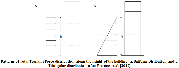
Patterns of Total Tsunami Force distribution along the height of the building: a. Uniform Distribution and b. Triangular distribution after Petrone et al. [2017].
Variables for Phase 1 (VDPO)
The only variable to be defined for the VDPO analysis phase is the number of steps to be used for the VDPO analysis
Variables for Phase 2 (CDPO)
For phase 2 (CDPO) the user needs to define whether the CDPO analysis will be performed or not, the maximum deformation ratio achieved during the CPDO analysis (ratio with the deformation of the control node at the start of the CDPO analysis), and the number of steps in which the CDPO analysis is to be carried out.
Tsunami Loaded Nodes
In the table with all the nodes of the building, the user needs to define which nodes are loaded by the Tsunami force. The part of the Total Tsunami force attributed to a certain group of nodes with identical height will be then distributed to the selected nodes belonging to the particular group.
When all the variables are defined the user can select the “Calculate Tsunami Load” button and execute the calculation of the inundation depth/velocity and Tsunami Total Force time-series and distribute the Total Tsunami Force on the Loaded Nodes. The Tsunami Force time-series for the VDPO analysis phase will be introduced in the “Time-history curves” tab and the Static Time-history nodal loads for the VDPO analysis phase will be introduced in the Applied Loads tab of the program. Finally selecting the “Basic Tsunami Parameters” button will open a window presenting the time histories of the main Tsunami Analysis parameters including the inundation depth, the flow velocity, the Froude number and the Tsunami Total Force.