Slab
On the slab’s Properties Window users can define (i) the section’s height, (ii) the reinforcement and its rotation to the X & Y axes and (iii) its self weight and the additional permanent, live and snow loads; the latter is required only by ASCE 41-23 and TBDY. The self-weight of the slabs may be automatically calculated and included in the structural model or a user-defined value may be used. The slab's live loads are automatically assigned by the program after the user selects the appropriate type of loaded area from the corresponding module or define them.
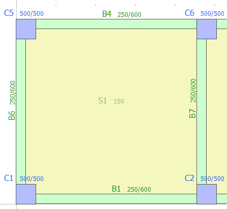
A slab can be defined with a single mouse click on any closed area surrounded by structural members (columns, walls and beams).
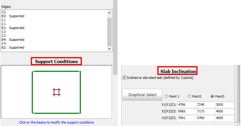
After defining a slab, users may modify its support conditions, thus adjusting which beams the slab loads are to be distributed. Further, the inclination of the slab may be modified by specifying the slab elevation at three points that can be graphically selected. The neighboring beams’ elevation and column heights are automatically adjusted, whereas the columns are subdivided in shorter elements by the program, if this is required, i.e. in the cases where two or more beams are supported by the same column at different levels, thus creating short columns.
For guidelines on how to insert a slab click here.
Notes
- The slab reinforcement is applied to the effective width of the beams at the perimeter of the slab. Obviously, when users select not to include the effective width in the modelling, such reinforcement settings become redundant.
- The slab modelling is carried out with rigid diaphragms; hence, a rigid slab is implicitly considered in the structural configuration, which is the case for the vast majority of RC buildings. The slab’s loads (self weight, additional gravity and live loads multiplied by the corresponding coefficients in the Static Actions module) are transformed to masses, based on the g value, and applied directly to the beams that support the slab.