Selecting the calculation method
In SeismoArtif, users can choose from four calculation methods for the simulation of artificial ground motions. These methods are listed below:
- Synthetic Accelerogram Generation & Adjustment
- Artificial Accelerogram Generation
- Artificial Accelerogram Generation & Adjustment
- Real Accelerogram Adjustment
Synthetic Accelerogram Generation & Adjustment method is the default option. Synthetic accelerograms tend to appear realistic and they can be generated with some basic (or more extended) knowledge of earthquake history and soil conditions relative to the region/site of interest. This method is able to efficiently combine simple input data with good results.
Artificial Accelerogram Generation and Artificial Accelerogram Generation & Adjustment methods are based on the adaptation of a random process to a target spectrum. The target spectrum is the only data necessary for the generation of an accelerogram in these cases. However they require experience for the assessment of the appropriateness of the generated accelerogram.
In Real Acceleration Adjustment method, the artificial accelerogram is defined starting from a real one and adapting its frequency content to match the target spectrum using the Fourier Transformation Method.
The different methods call for different input modules, as a function of the parameters required for the artificial accelerograms generation. The Target Spectra module is common to all of the methods.
Synthetic Accelerogram Generation & Adjustment
Synthetic accelerogram generation [Hallodorson & Papageorgiou, 2005] and correction in frequency domain
This is the default calculation method given by the software and it is based on Hallodorson & Papageorgiou [2005] algorithm. The artificial accelerogram is defined starting from a synthetic one (simulated by the user), compatible with the target spectrum, and adapting its frequency content using the Fourier Transformation Method.
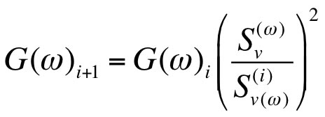
The correction of the random process is carried on at every iteration using the relationship below [Mucciarelli et al., 2004]:
![]()
SRT(f) is the value of the target spectrum and SR(f)i is the value of response spectrum corresponding to the accelerogram of the current iteration for frequency f. F(f)i+1 and F(f)i are the values of the accelerogram in the frequency domain for the current and previous iteration respectively. At each iteration a Fourier Transformation is applied to move from time domain to frequency domain, where the correction to the accelerogram is carried on. Then an Inverse Fourier Transformation is applied in order to return to the time domain, where the corresponding spectrum is calculated, convergence is checked and it is evaluated whether or not further correction is needed. A schematic summary is given below.
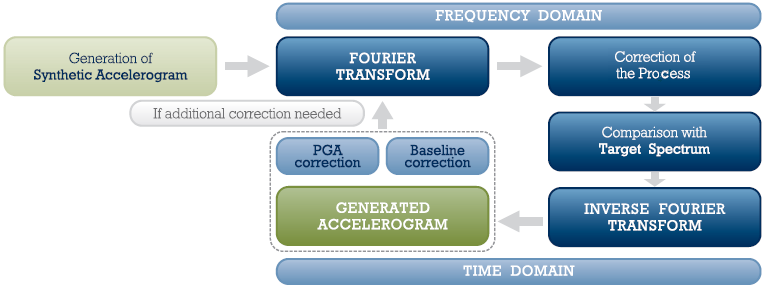
In this calculation method framework, the Envelope Shape module is not explicitly shown to the user, since the procedure does not start from a random process, but rather from a synthetic accelerogram.
The generation of the synthetic accelerogram starts from a Gaussian white noise which is multiplied by Saragoni & Hart [1974] envelope shape and then adapted to a certain source spectrum. The duration of the ground motion is calculated from the input parameters.
Accessing the Artificial Accelerogram Generation module, users can then define the parameters needed for the accelerogram simulation.
Artificial Accelerogram Generation
Random set of phase angles with amplitudes calculated by power density function [Gasparini & Vanmarcke,1976]
This method defines each artificial ground motion modifying the starting random process through the use of a selected envelope shape and a Power Spectral Density Function (PSDF). The PSDF is calculated from the velocity target spectrum (Sv) which is selected before the execution.
This calculation method is based on the fact that each periodic function can be expressed as a series of sinusoidal waves as given in the following formula:
![]()
where An is the amplitude and Φn is the phase angle of the nth sinusoidal wave. Defining a vector of amplitudes and simulating different arrays of phase angles, it is possible to obtain different processes with the same general aspect but with different characteristics. Such processes are stationary (or steady-state) and their characteristics do not change with time.
To simulate the transient nature of the earthquakes, the steady state motions are multiplied by a deterministic envelope shape (or intensity function) I(t), selected by the user in corresponding Envelope Shapes module.
The artificial ground motion is then defined as:
![]()
These amplitudes are calculated using the PSDF. In this calculation method, the phase angles are generated in the interval [0 2Π], following a Uniform probability distribution. The amplitudes (i.e. An) are related to the (one-sided) PSDF G(ω) as follows:
![]()
G(ω)Δω represents the contribution to the total power of the motion from the sinusoid with frequency ωn. If the number of sinusoidal waves considered in the motion is very large, the total power will become the area under the continuous curve G(ω), as given in the formula below:
![]()
The resulting motion is stationary in frequency content, with a peak acceleration close to the target one. The response spectra, relative to the generated motion, are then computed and the program will attempt to match them against the selected target spectrum.
This artificial accelerogram generation method is iterative. For each cycle (i), the response spectrum generated for the simulated ground motion, is compared with the target (at a set of control frequencies). The ratio between the desired response and the computed response is defined at each cycle and the corresponding Power Spectral Density Function (PSDF) is recalculated as a function of the square of the aforementioned ratio as indicated in the following formula:
where Sv is the target spectrum value (i.e. desired response values) and Sv(i) (i.e. computed response values). Using the modified PSDF, a new motion is simulated and a new response spectrum is calculated or, otherwise, the procedure can be repeated automatically with new random processes until convergence. A schematic summary of this method is given in the figure below.
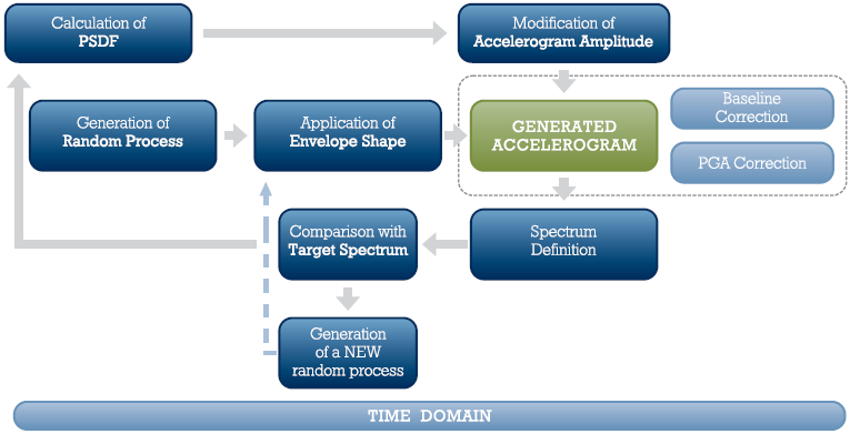
The software automatically carries on the entire iterative procedure. N executions with different (Nω) phase angles are performed until convergence is reached. The default values are N=3 and Nω=100 as can be noted in the Program Settings module of the software. If convergence cannot be reached, SeismoArtif will output the best solution.
Accessing the Artificial Accelerogram Generation module, users can then define the parameters needed for the accelerogram simulation.
Artificial Accelerogram Generation & Adjustment
Random process adjustment by correction in frequency domain
This method defines the artificial ground motions considering a target spectrum and adapting the frequency content using the Fourier Transformation Method. It can be considered as an evolved version of the one described above. Indeed, the generation of the random process and the application of the envelope shape are common to the Artificial Accelerogram Generation method, with its main distinctive feature being the correction (at each iteration) of the random process in the frequency domain. A schematic summary is given below.
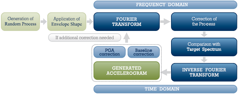
Input parameters and output results are the same of the Artificial Accelerogram Generation method, but this is more stable and one-sided and more likely to lead to a very good convergence (error less than 7-8%), at the expense of a higher number of iterations, however.
Accessing the Artificial Accelerogram Generation module, users can then define the parameters needed for the accelerogram simulation.
Real Accelerogram Adjustment
Real accelerogram adjustment by correction in frequency domain
The artificial accelerogram is defined starting from a real one and adapting its frequency content to match the target spectrum using the Fourier Transformation Method as described in more detail here. This method may lead to reasonable results, however the more the target response spectrum differs from the real accelerogram's spectrum, the less realistic the artificial accelerogram will be. Indeed, users who wish to employ existing real accelerograms in the derivation of spectrum-compatible ground motions, something which is certainly recommended, are strongly suggested to use SeismoMatch instead, a more valid and appropriate tool for this purpose.
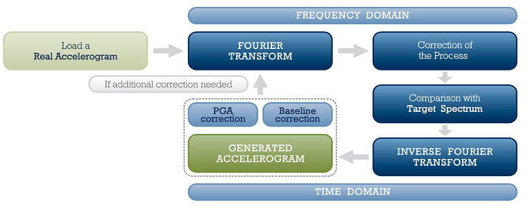
The real accelerogram should be loaded as text file from the Real Accelerogram module, clicking the Open Real Accelerogram button.
In this calculation method framework, the Envelope Shape module is not explicitly shown to the user, since the procedure does not start from a random process, but rather from a real accelerogram.
Accessing the Artificial Accelerogram Generation module, users can then define the parameters needed for the accelerogram simulation.