Insert Steel Columns
A steel column may be inserted from the main menu (Insert >...) or through the corresponding toolbar button  .
.
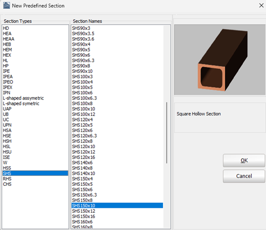
On the Properties Window that appears users select one section from the predefined standard sections.
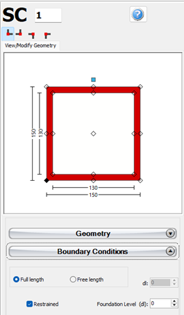
It is possible to define a steel column height different from the storey height by selecting the Free length radio button and assigning the value of the height difference. Further, it is possible to adapt the foundation level of columns at the ground floor, thus providing the possibility to the user to define buildings with varying foundation levels.
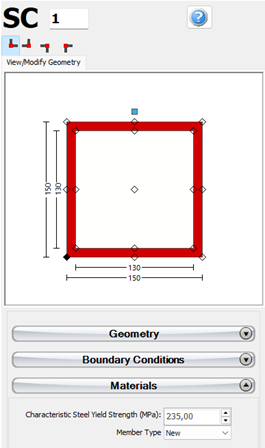
The steel’s properties can be defined within the member’s Properties Window. The characteristic steel yield strength and the type of the members, i.e. existing or new member, should be defined..
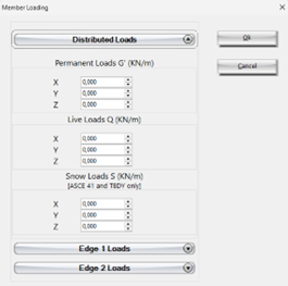
Additional loads can be defined by clicking on the Distributed and Edge Loads button. Users can define uniform distributed forces along the length of the member in all three translational directions X, Y or Z, and forces or moments in any translational or rotational direction (X, Y, Z, RX, RY or RZ) at either of the two edges of the member (bottom or top). Additional permanent loads G’ (not associated with the self-weight of the structure), live Q and snow S loads may be applied, with the latter being applicable only to ASCE 41 and TBDY. By default all loads are equal to zero.
Isolators can also be added at different locations of the column. They are assigned through the Isolator module, where the users may select the geometry (location -bottom, top or intermediate point- and the height of the isolator), its type (elastomeric, lead rubber or curve surface slider) and the isolator parameters: the vertical and horizontal stiffnesses, and the shear yield strength and the strain hardening ratio (for elastomeric and lead rubber isolators, which are modelled as isolator1) or the friction coefficient and the radius of the pendulum (for curve surface sliders, also known as Friction Pendulum System (FPS), which are modelled as isolator2).
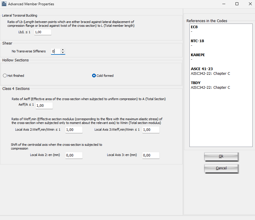
The code-based settings of the structural member can be defined through the Advanced Member Properties dialog box that opens from the corresponding button.
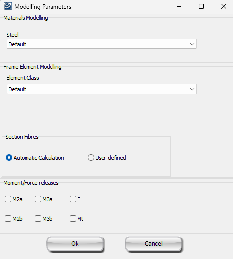
The modelling parameters of the structural member can also be defined through the Modelling Parameters dialog box that opens from the corresponding button.
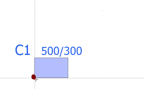
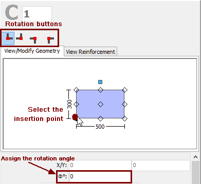
Finally, the insertion point (point of the section that corresponds to the location of the mouse click) may be chosen by clicking on the corner, middle or side points of the section's plot on the Properties Window, whereas the rotation of the column on plan-view can be changed by the 0o, 90o, 180o and 270o buttons or by assigning the proper angle on the corresponding of editbox of the Properties Window.
After defining all the section's properties, the new member may be added graphically with a simple mouse click on the building's plan view.
.